Image display

a technology for image displays and display panels, applied in the field of image displays, can solve the problems of reducing the efficiency of heat radiation or dissipation of display panels, reducing the thickness of image displays, and reducing the thickness of image displays. , to achieve the effect of reducing the thickness of image displays, reducing the thickness of display panels, and high-quality design

Active Publication Date: 2012-11-27
MAXELL HLDG LTD
View PDF59 Cites 73 Cited by
  • Summary
  • Abstract
  • Description
  • Claims
  • Application Information

AI Technical Summary

Benefits of technology

[0005]Demand has increased in recent years for reduced thickness of image displays, in combination with high-brightness and high-definition. In order to achieve a high-quality design, as well as to achieving an ease of wall hanging (i.e., hanging the image display on a wall for the purpose of viewing / listening), it is necessary to achieve further thickness reduction and weight reduction, in comparison to existing thin-type image displays.
[0006]In order to achieve thickness reduction, it is necessary to reduce the thickness of a space on a rear surface thereof, which occupies most of the depth of the image display. With this thickness reduction of the rear surface, in combination with the thickness reduction of the various kinds of substrates and / or members to be installed, it is necessary to reduce the distances defined between the various kinds of substrates and a base chassis for supporting the display panel thereon, and also the distance defined between the various kinds of substrates and the cover on the side of the rear surface.
[0008]In this instance, there is a necessity of installing a new insulator member between the substrates and the chassis. The structure for installing a plate-like insulator board as the insulator member is simple (from a structural viewpoint). However, the insulator board has a very low thermal-conductivity of around 0.1 to 1 (W / m·° K), compared to the thermo conductivity of the chassis made of a metal material (such as: an iron alloy or an aluminum alloy, etc.), in many cases having a thermal-conductivity of around 30 to 200 (W / m·° K). For this reason, the insulator board on the base chassis prevents a flow of heat dissipation into air within the inside of the image display, from the display panel through the chassis. As a result, there is a problem that an efficiency of heat radiation or dissipation of the display panel is further reduced, in particular via the chassis in the portion where the insulator board is provided.
[0011]Also, within a conventional image display, opening(s) are often provided in a middle portion of the rear surface cover (not only in the upper side and the lower side of the rear surface cover), for the purpose of improving heat radiation or dissipation due to accelerating suction / exhaustion of air from / into an outside of the apparatus. However, when providing opening(s) in the middle portion of the rear surface cover, there result new problems, in that the design quality or characteristic of the apparatus is reduced, and that it becomes difficult to block or shield propagation of the sound noises of the fan inside the apparatus and electromagnetic noises from a substrate for a power source.
[0012]An objective of the present invention is to provide an image display for increasing or improving the cooling efficiency of: the display panel, various kinds of substrates, and / or image display elements of within the thin-sized image display; but without an accompanying increase of fan noises.
[0014]According to the present invention, it is possible to cool the heat generating parts (such as: a display panel, display driver substrates, and a image display element, etc.), with stability, while suppressing noises heard outside of the apparatus; and also to maintain electrical insulation among: circuit parts, a chassis, and a non-display side cover. Accordingly, it is possible to provide an image display having high-brightness and high-definition, as well as high reliability, and also having easy wall hanging installation and high design quality.

Problems solved by technology

Therefore, there is a problem that heat radiation of the display panel through the chassis is reduced.
Furthermore, because the distance between the substrates and the chassis becomes smaller, the necessary distance cannot be maintained for obtaining an insulation between circuit parts which are installed on the substrates and the chassis.
As a result, there is a problem that an efficiency of heat radiation or dissipation of the display panel is further reduced, in particular via the chassis in the portion where the insulator board is provided.

Method used


Image

  • Image display
  • Image display
  • Image display

Examples


embodiment 1

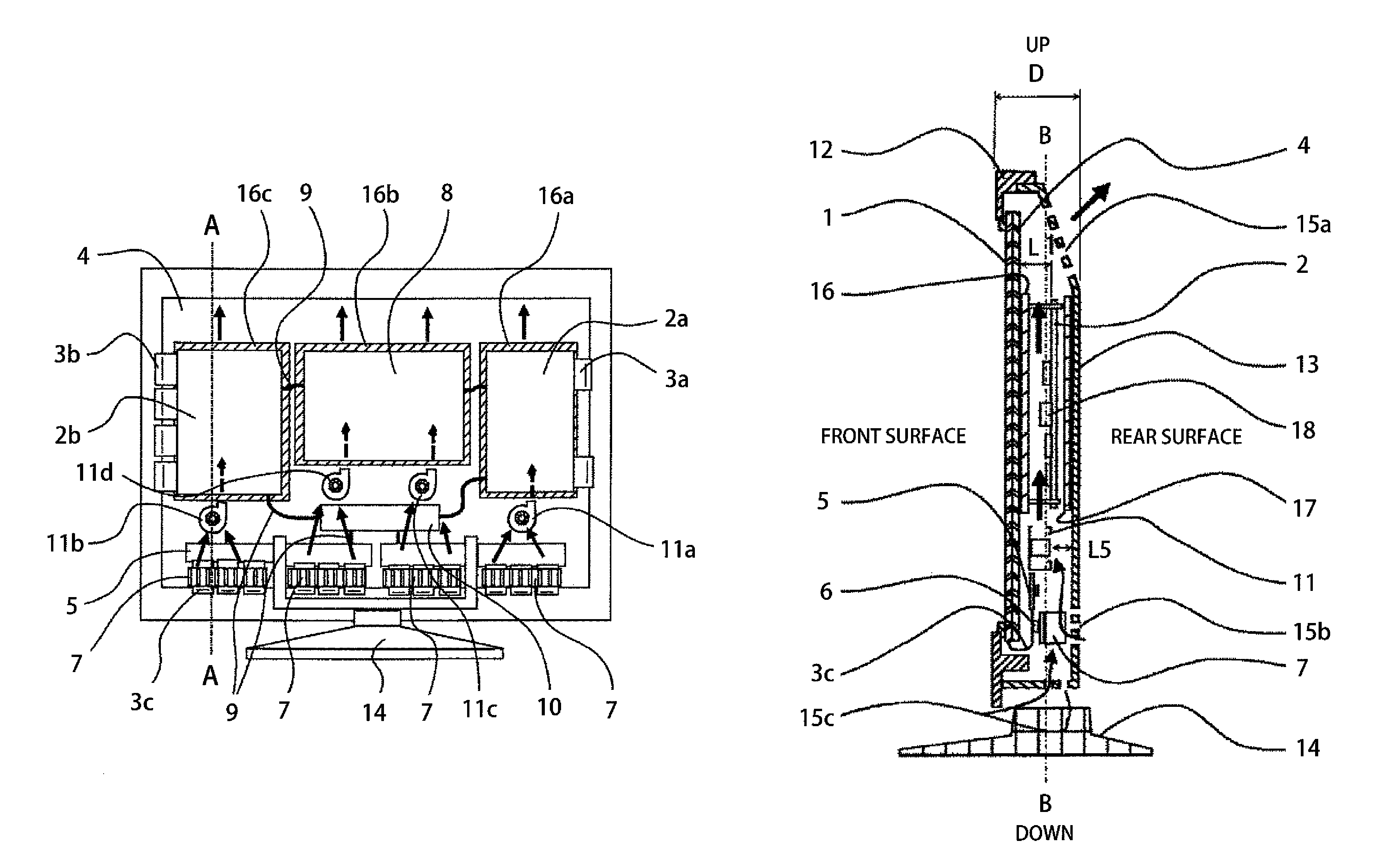
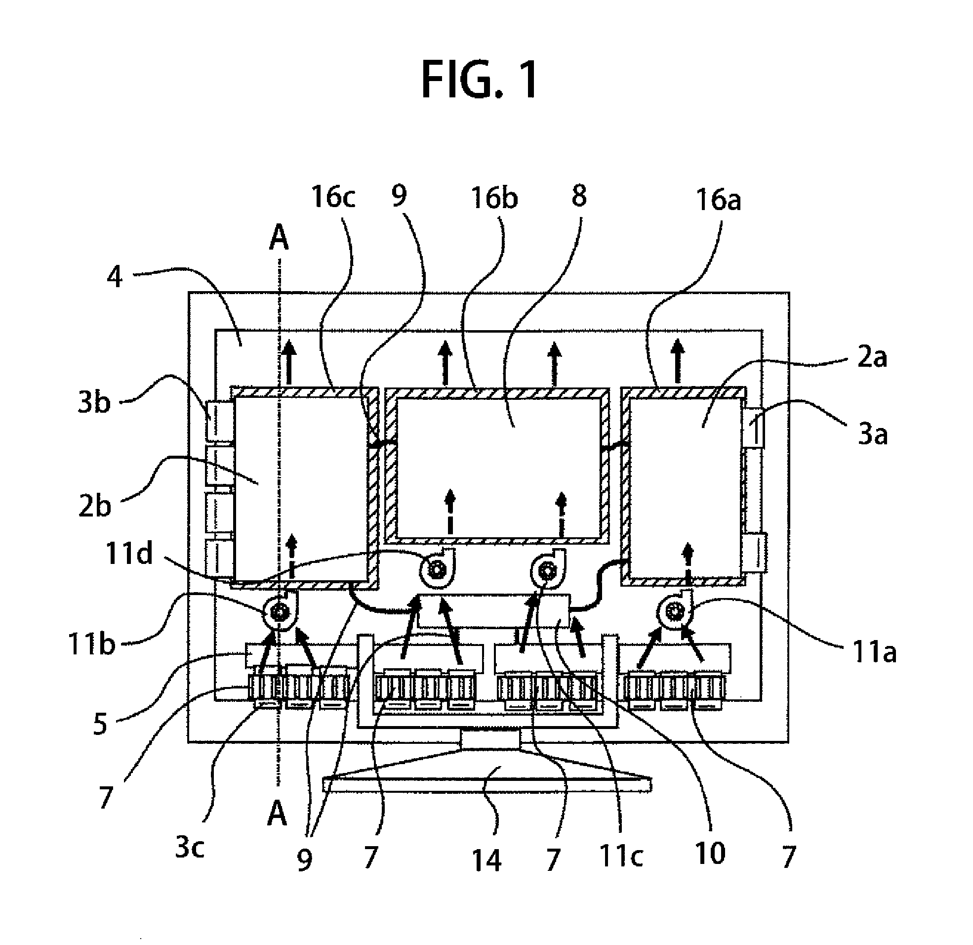
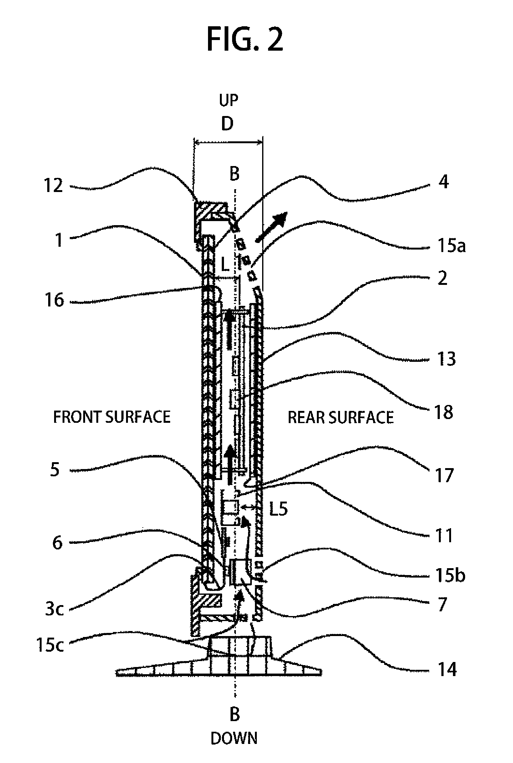
[0035]Hereinafter, explanation will be made on an embodiment 1, by referring to the FIGS. 1 to 13 attached herewith. FIG. 1 is a rear side open-up view showing the principle portions of an image display, according to an embodiment 1 of the present invention. FIG. 2 is an A-A cross-section view of the image display, seeing from a side surface in FIG. 1. FIG. 3 is an outlook view of a rear surface side of the image display shown in FIG. 1. FIG. 4 is a view showing a cover of the image display on the rear-surface side, seen from an inside of a housing shown in FIG. 1. FIG. 5 is a B-B cross-section view showing the image display shown in FIG. 2, seen from a rear surface thereof. FIG. 6 is a C-C cross-section view showing the image display shown in FIG. 5. FIG. 7 is a cross-section view of the conventional structure of the image display, corresponding to the A-A cross-section in FIG. 1. FIG. 8 is a rear surface view of the image display of the conventional structure. FIG. 9 is a view sho...

embodiment 2

[0063]Embodiment 2 will be explained by referring to FIGS. 14 to 16. FIG. 14 is a view showing distribution of temperatures on a front surface of a display panel of the structure according to embodiment 1. FIG. 15 is a rear side open-up view showing the principle portions of an image display, according to an embodiment 2 of the present invention. FIG. 16 is a F-F cross-section view of the image display, seen from a side surface in FIG. 15. However, sizes of the display driver substrates 2a and 2b and the power source substrate 8 are shown by broken lines in FIG. 15.

[0064]With embodiment 2, as shown in FIGS. 15 and 16, among the circuit parts installed on the display driver substrates 2a and 2b, first insulator boards 16d, 16e and 16f are provided at the positions opposite to the positions of installing the circuit parts, each having height at least equal or greater than 50% of the height “H5” from the display driver substrates 2a and 2b (i.e., at least equal or greater than 50% with...

embodiment 3

[0071]Embodiment 3 will be explained by referring to FIGS. 17 and 18. FIG. 17 is a rear side open-up view showing the principle portions of an image display, according to embodiment 3 of the present invention, and is showing a G-G cross-section of FIG. 18. FIG. 18 is a H-H cross-section seeing the H-H cross-section from a side surface.

[0072]In FIGS. 17 and 18, reference numerals 26a, 26b ad 26c depict plate-like members made of high thermal conductivity, and in particular, a material having a thermal conductivity higher than the thermal conductivity of the chassis 4, in the direction of in-plane thereof. Though the chassis 4 is made of a metal member such as: an iron alloy or an aluminum alloy, etc., in many cases, having the thermal conductivity of around 30 to 200 (W / m·° K), however it is possible to obtain the thermal conductivity of 400 to 700 (W / m·° K) in the in-plane direction thereof, if applying a graphite sheet obtained by processing graphite into the sheet-like shape.

[0073...


PUM


Abstract

For improving a cooling efficiency of a display panel in a flat-type image display, various substrates and an image display element are disposed within a thin-sized housing thereof, including: a display panel; a chassis supporting the display panel from a rear surface side thereof; a front surface-side cover on a front side of the display panel; a rear surface-side cover on a rear side of the display panel; an image display element connected to the display panel; a display driver substrate connected to the display panel, and on a surface thereof opposite to the chassis are provided circuit parts; a power source substrate, supplying driving power to the display driver substrate and the image display element, and on a surface thereof opposite to the chassis are provided circuit parts thereof; and a first insulator board opposite to the display driver substrates and the power source substrate of the chassis.

Description

BACKGROUND OF THE INVENTION[0001]The present invention relates to an image display, and in particular, to cooling for display panels (such as: a plasma display, a LCD display, an OLED display, etc.), for example, and / or cooling for various kinds of boards, and image processing elements thereof, as well.[0002]For a flat-type image display (such as a plasma display and a liquid crystal display, etc.), high-brightness and high-definition of images or pictures are required, and with an increase of a number of electronic parts used for image processing, heat generated by the display panel and various kinds of substrates also increases. Therefore, cooling of such heat generating parts becomes a problem to be solved.[0003]A display described in Patent Document 1 [Japanese Patent Laying-Open No. 2005-235843 (2005)] achieves a solution for said heat generation problem of the display panel module and the various kinds of substrates. Patent Document 1 discloses structures for conducting the co...

Claims


Application Information

Patent Timeline
Patent Type & Authority Patents(United States)
IPC IPC(8): H05K7/20
CPCH05K7/20972
Inventor ISOSHIMA, NOBUYUKIMIYOSHI, KOHEIRI, MIKAYAMADA, YUTAKATSUTSUI, TOSHIHIROTANAKA, TEPPEIKUBOTA, HIDENAONISHINAKA, YUZO
Owner MAXELL HLDG LTD
Why Eureka
Try Eureka