Switching power source device and drive method thereof

a technology of switching power source device and drive method, which is applied in the direction of electric variable regulation, process and machine control, instruments, etc., can solve the problems of affecting the spread of digital control switching power source device with excellent intelligence, high-performance digital processor which operates at a high-speed clock is necessary, and achieves automatic adjustment of overcurrent protection characteristics, high speed, and superior intelligence

Active Publication Date: 2012-11-27
COSEL
View PDF10 Cites 14 Cited by
  • Summary
  • Abstract
  • Description
  • Claims
  • Application Information

AI Technical Summary

Benefits of technology

[0014]The invention, being contrived bearing in mind the heretofore described background art, has an object of providing a switching power source device, and drive method thereof, which has a superior intelligence, has a high-speed responsiveness of a level equivalent to or higher than an analog control, even while using a comparatively low-cost general purpose digital processor, or the like, and also includes a digital control overcurrent protection function which can obtain a highly accurate overcurrent protection characteristic.
[0027]According to the switching power source device of the invention, it is possible to realize a digital control overcurrent protection circuit with superior intelligence which can respond at a high speed, using a low-cost digital processor with a comparatively low-speed clock. In particular, it is also possible to carry out an optimum overcurrent protection control in response to a fluctuation of an external temperature, input voltage, output voltage, and the like. Furthermore, it being possible to automatically adjust the overcurrent protection characteristics in line with an individual difference in the characteristics of the discrete parts, and the like, configuring the switching power source device, and with a usage condition of the switching power source device, it is possible to ensure the safety of the load electronic instrument, and of the switching power source device itself. Then, it is possible to provide a small, low-cost switching power source device.
[0028]Also, according to the drive method of the switching power source device of the invention, it is possible to programatically adjust the overcurrent protection characteristics in line with an individual difference in the characteristics of the discrete parts, and the like, configuring the switching power source device, setting them to an optimum condition. Furthermore, it being possible reduce processes such as a resistance value adjustment or part replacement, the overcurrent protection and safety of the load electronic instrument, and of the switching power source device itself, are ensured with a simple circuit configuration, enabling a stable power source drive.

Problems solved by technology

However, with the overcurrent protection circuit disclosed in Patent Document 1, when mounting it in a current, practical switching power source device, there is a problem in that in order to obtain control characteristics which enable a high-speed response to a precipitous increase in the output current, a high-cost digital processor which operates with a high-speed clock is necessary.
A high-performance digital processor which operates at a high speed in this way is extremely expensive.
Consequently, there is a cost-related problem in employing a digital control in a general purpose switching power source device, which is hindering the spread of a digital control switching power source device with excellent intelligence.

Method used


Image

  • Switching power source device and drive method thereof
  • Switching power source device and drive method thereof
  • Switching power source device and drive method thereof

Examples


first embodiment

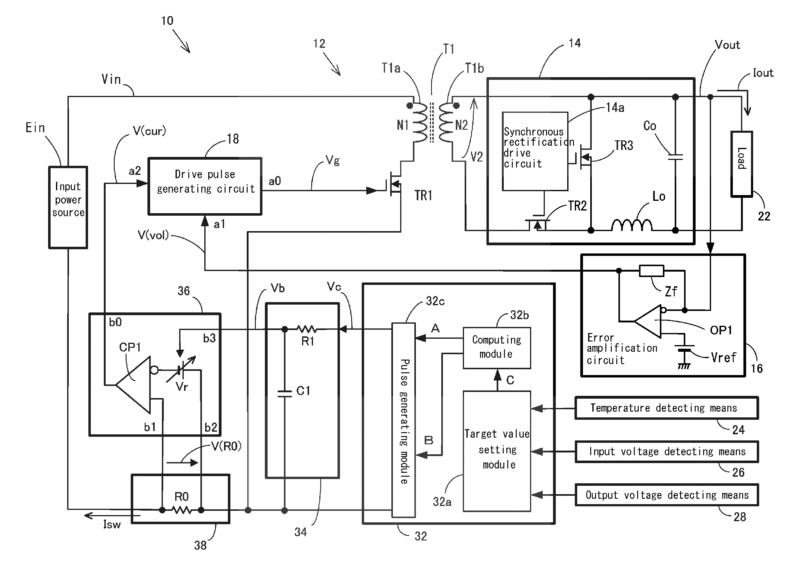
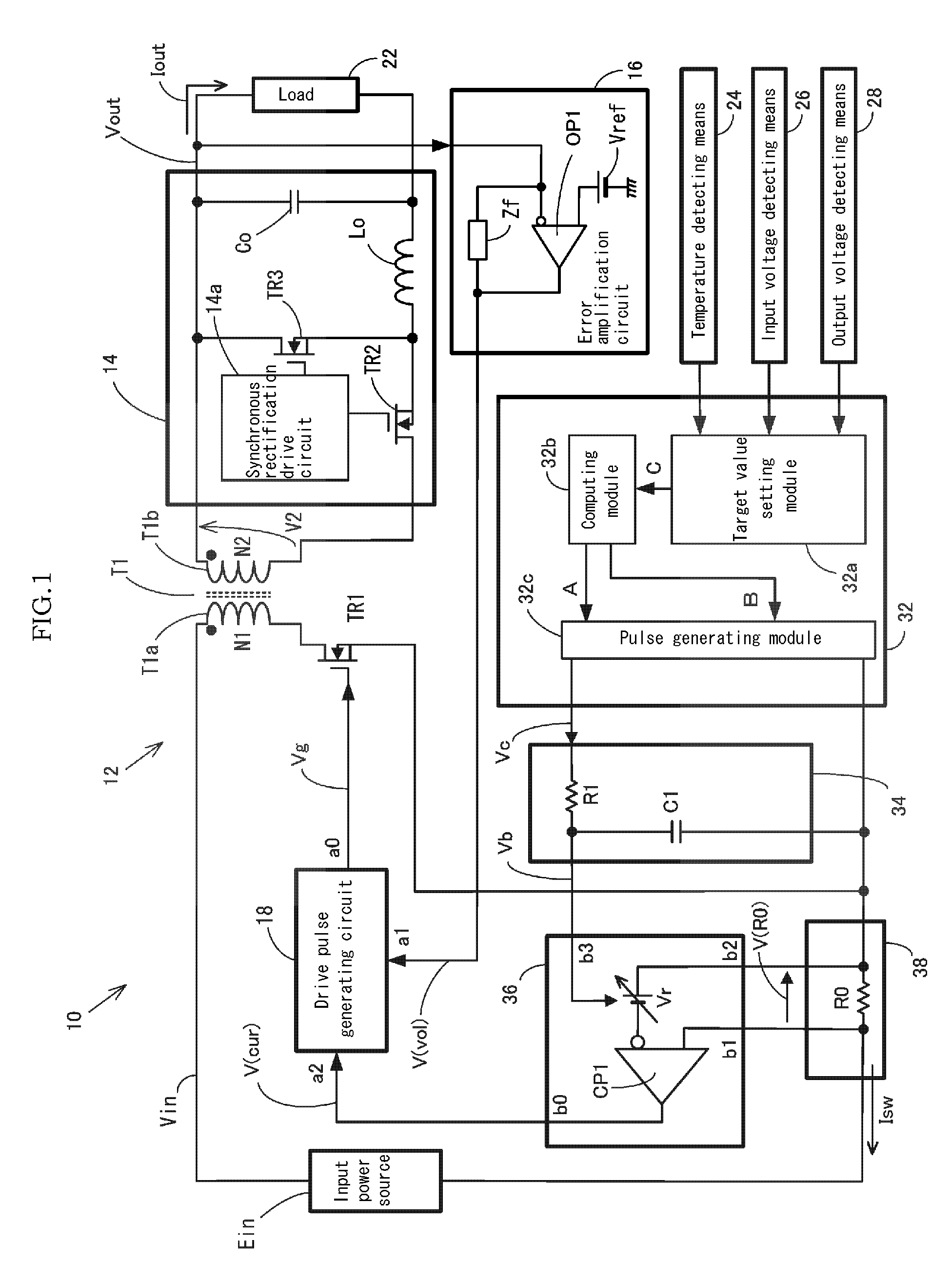
[0058]Hereafter, a description will be given, based on FIGS. 1 to 6, of a switching power source device of the invention. Firstly, a description will be given of an outline, based on the overall circuit diagram shown in FIG. 1. A switching power source device 10 includes an inverter circuit 12 to which a direct current input power source Ein is connected, and which generates an alternating current voltage V2 in accordance with an on-off operation of a switching element TR1, and a rectification and smoothing circuit 14 which rectifies and smoothes the alternating current voltage V2, generating an output voltage Vout, and an output voltage Vout terminal is connected to a load 22. The output voltage Vout is connected to an error amplification circuit 16 configured of an inverting amplifier which outputs an output voltage control signal V(vol), wherein a difference between the output voltage Vout and a predetermined reference voltage Vref is amplified. Furthermore, the switching power s...

second embodiment

[0093]Next, a description will be given, based on FIGS. 7 to 9, of the switching power source device of the invention. Configurations identical to those of the heretofore described switching power source device 10 will be given identical reference numerals and characters, and a description will be omitted. Firstly, a description will be given of an outline, based on the overall circuit diagram of FIG. 7. A switching power source device 50 includes an inverter circuit 12 to which a direct current input power source Ein is connected, and which generates an alternating current voltage V2 in accordance with an on-off operation of a switching element TR1, and a rectification and smoothing circuit 14 which rectifies and smoothes the alternating current voltage V2, obtaining an output voltage Vout, and an output voltage Vout terminal is connected to a load 22. The output voltage Vout is connected to an error amplification circuit 16 configured of an inverting amplifier which outputs an out...

fifth embodiment

[0128]Next, a description will be given, based on FIG. 12, of a fifth embodiment, which is a modification example of the drive pulse generating circuit 18 of the switching power source device of the invention. In a drive pulse generating circuit 62 of the embodiment, as the charging resistor R11 of a sawtooth wave generating circuit 62b is connected to the input voltage Vin, the gradient at which the sawtooth wave voltage V(osc) rises changes in proportion to the input voltage. Because of this, a feed forward control according to the fluctuation of the input voltage is added to the feedback control of the output voltage, and a high-speed responsiveness of an output voltage stabilizing control increases.

[0129]Furthermore, a voltage generating element Rb, at which a voltage proportionate to the input voltage is generated, is inserted at a midpoint of the timer capacitor C11 and charging resistor, and a total value of the voltage generated at the timer capacitor C11 and voltage generat...


PUM


Abstract

A switching power source device includes current control pulse generating means configured of a target value setting module, which outputs a changeable value which is a predetermined target value relating to a control of an output current, a computing module, which carries out a computing process relating to the control of the output current based on the target value, and outputs a computation result, and a pulse generating module, which generates a current control pulse voltage for controlling the output current based on the computation result. The switching power source device includes a current detecting circuit, which detects the output current or a current flowing in a switching element TR1, and a current limit signal generating circuit which, when the detected current exceeds a reference value set based on the output of the current control pulse generating means, outputs a current limit signal for limiting the current. A drive pulse generating circuit, on the current limit signal being output, operates in such a way that an on-duty of a drive pulse stops widening, or becomes narrower.

Description

[0001]This application is a U.S. National Phase Application under 35 USC 371 of International Application PCT / JP2008 / 071432 filed Nov. 26, 2008.TECHNICAL FIELD[0002]The present invention relates to a switching power source device which carries out a control of a switching operation with a pulse width modulation signal, converts a direct current voltage to a desired voltage, and supplies power to an electronic instrument, or the like, and relates in particular to a switching power source device, and drive method thereof, which control an output current with a digital control.BACKGROUND ART[0003]A general switching power source device is provided with an overcurrent protection circuit which limits its supply capacity so that there is no flow of an output current exceeding a predetermined value. The object of this is, as well as preventing an electronic instrument, or the like, from overheating or burning out due to an excessive current continuing to flow when the electronic instrument...

Claims


Application Information

Patent Timeline
Patent Type & Authority Patents(United States)
IPC IPC(8): H02M3/24
CPCH02M3/33507H02M1/32H02M3/33592Y02B70/1475Y02B70/10
Inventor HORII, KAZUHIRO
Owner COSEL
Why Eureka
Try Eureka