The increase of the maximal speed of flight is limited, mainly, due to the phenomena of stalling on the blade going against the direction of flight and besides, due to the phenomenon of
compressibility on the blade going in the direction of flight (E. I. Ruzhitsky, Vertical take-off
aviation, National publishing house of
defense industry, Moscow, 1959, p.
The increase of thrust of the air
propeller due to increase of rotational speed is limited by the increase of profile resistance of blades.
When flying at high speeds as increasing the
advance ratio of the
propeller the angles of incidence of the blades are also increased for maintaining the angles of
attack of blades, thus the forces created by the
propeller blades deviate closer to the plane of rotation, and the losses for swirling the
airflow behind the propeller grow.
There is another drawback inherent to propellers used in aircraft: when flying at high speeds they cannot create elevating force for balancing of masses in flight, thus they are used only for creating the thrust.
Therefore, the blades rotating upwards, create forces diminishing the speed.
As a result of such a use the propeller creates elevating force,however it does not create thrust, but creates resistance that leads to unjustified expenses of energy for creating thrust for overcoming the force diminishing the speed of the blade rotating upwards by jet engines, mounted at the ends of wings-blades while the thrust and elevating force may be created on the propeller.
Another drawback of the above method of flight is the significant moment transversal to axes of the propeller effecting on the propeller, which should be compensated aerodynamic rudders.
The drawback of the method of creation of elevating force used for flight, transversal to the axis of rotation of the propeller, when the axis is inclined under a small angle to the incident flow, for example, in the
vertical plane in horizontal flight, is that in case of rotation under wide angles to the horizontal position and blades close to vertical position the forces created on blades increase the thrust of the propeller, but do not make important contribution to create the lift.
The main problem of aircrafts using for flight the force transversal to the axis of propellers being in conditions close to axial flow, is creation of lift sufficient for flight and deflection of propeller force upwards, as well as impossibility to incline the axis at wide angles of
attack at high speeds of flight.
The drawback of the method of creation of elevating force used for flight, transversal to the axis of rotation of the propeller, when the axis is inclined under a small angle to the incident flow, for example, in the
vertical plane in horizontal flight, is that in case of rotation under wide angles to the horizontal position and blades close to vertical position the forces created on blades increase the thrust of the propeller, but do not make important contribution to create the lift.
The drawback of these aircrafts, such as X-100, X-19 and of the method of their flight, is that achievement of radial force directed transversally to the propeller axis, becomes possible only at high transsonic speeds of flight comparable to the
peripheral speed of propellers.
The drawback of the method of creation of elevating force used for flight, transversal to the axis of rotation of the propeller, when the axis is inclined under a small angle to the incident flow, for example, in the vertical plane in horizontal flight, is that in case of rotation under wide angles to the horizontal position and blades close to vertical position the forces created on blades increase the thrust of the propeller, but do not make important contribution to create the lift.
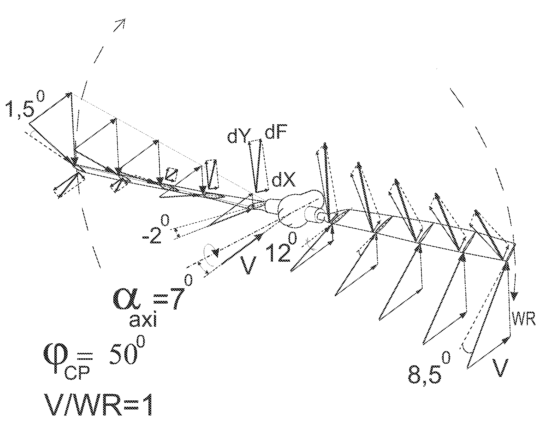
The use of angles of the axis of propellers close to 10°, in case of rotation of the blade upwards in horizontal flight leads to occurrence of negative angles of
attack of blades that reduces the thrust of the propeller while increasing the force in the plane of propellers.
This leads to unjustified expenses for overcoming the force diminishing the speed arising on blades on these areas of the propeller.
Use of smaller angles of axes to the flow, not resulting to formation of a reversal area, leads to redundant thrust when creating the lift necessary for maintaining the weight.
Thus the drawback is limitation of the axis angle with respect to the flow direction in case of flight of an aircraft at high speeds, the phenomena of shock stall at high angles of the axis with respect to the flow and
initiation of an area of thrust reversion on the propeller.
The
narrow range of angles of the propeller axis with respect to the flow providing the possibility of flight, complicates the transition from flight with the axes located vertically, to flight with the axes located in the direction of horizontal flight.
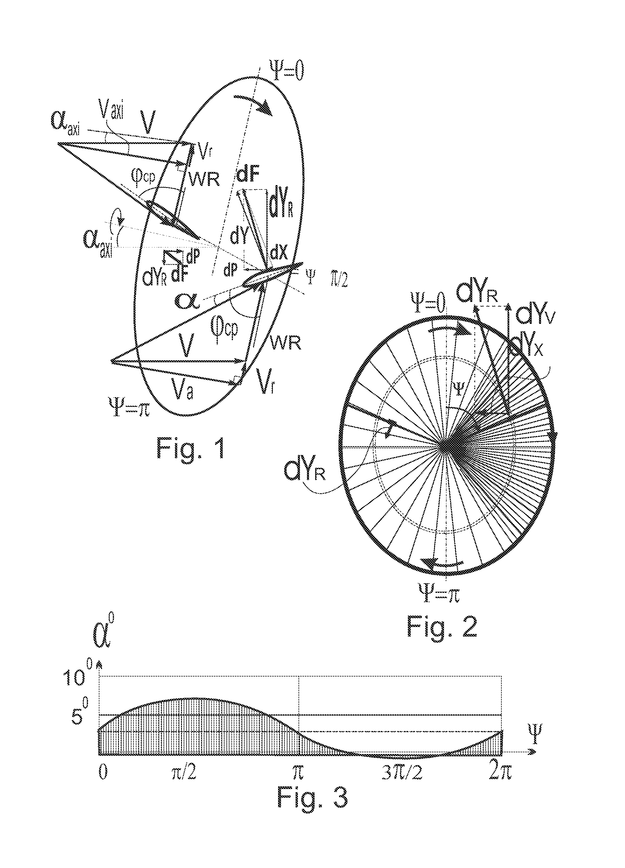
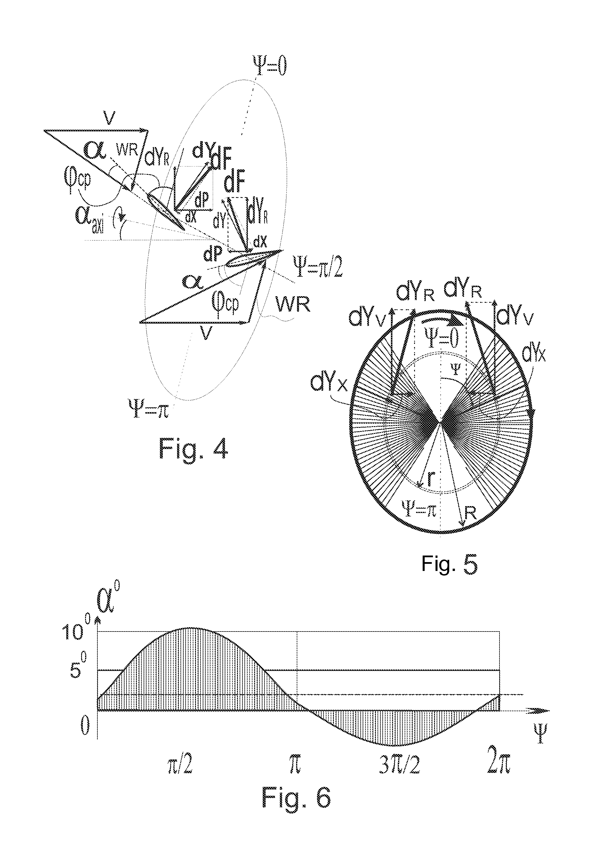
The lift fluctuations on each blade lead to oscillations of the blade with the propeller rotation frequency, thus increasing tension in the blade.
The drawback is that propellers develop significant radial force only at high speeds of flight when speeds of flight become comparable to
peripheral speed of rotation of propellers.
The drawback of the method of creating the lift used for flight, transversal to the axis of rotation of the propeller, in case of deflection of the axis under a small angle to the incident flow, for example, in the vertical plane in horizontal flight, is that when rotating under wide angles to the horizontal and blades position close to vertical the forces build on the blades increase the thrust of the propeller, but do not make significant contribution for the lift.
Decrease in thrust and increase in force, transversal to axes of propellers, as well as the lift allows to get the flight on propellers with normal for propellers high
peripheral speed of rotation, but this leads to unjustified expenses for overcoming the forces diminishing the speed, arising on the reversing portion of the propeller.
Use of smaller angles of axes to the flow, not resulting in reversal area, results in lift necessary for maintaining the weight, the thrust value would be redundant, and for reducing the latter it is required to reduce the angles of installation of the propeller blades that may lead to negative angles of attack and the reversal area on a part revolution when at rotating the blade upwards in horizontal flight.
Thus the drawback is limitation of the angle of axis to the flow direction at flight of the aircraft at a high speed, the phenomena of shock stall at high angles of axis to the flow and an area of power reversion on the propeller.
The
narrow range of angles of axis of propeller to the flow where the flight is possible, complicates the application of this method for transition from vertical take-off with axes located vertically, to flight with the axes located in the direction of horizontal flight.
Creation of a part of lift using a wing leads to additional thrust power expense for overcoming the wing resistance when all the necessary forces for flight may be created on propellers.
Developing aircrafts having such a position of main rotor have some difficulties due to obtaining a sufficiently
high lift regarding the thrust.
However the lift, sufficient for flight at the mentioned speeds, was obtained only at high speeds of flight thus complicating the transition to flight using radial force without wing support.
Using the supporting wing alongside with propellers increases the weight and resistance of the aircraft, and also results if arranging the propellers at the end of a wing, to additional oscillations in the wing design.
The main drawback of the offered methods of creating of force, transversal to the propellers axis in the axial flow, is the impossibility of creating an enough the
high lift in horizontal flight, due to creating a force, being transversal to the propellers axis.
A low efficiency of expenses of capacity for creating a thrust when creating a thrust on the propeller.
The drawback is the limitation of the angle of axis to the flow direction when flying at high speeds with the phenomena of shock stall and occurrence of an area of power reversion on the propeller.
Besides, the conditions of use of the method allowing to achieve the absence of shock stall on the blades are not determined, the conditions of use of the method allowing to achieve the absence of sectors of the power reversion are not determined as well.

