Device to transfer high frequency electrical signals between a rotating component and a stationary component

a technology of high frequency electrical signals and rotating components, applied in the direction of cables between relatively moving parts, instruments, applications, etc., can solve problems such as data loss and experience wear

Inactive Publication Date: 2012-12-25
SIEMENS HEALTHCARE GMBH
View PDF5 Cites 1 Cited by
  • Summary
  • Abstract
  • Description
  • Claims
  • Application Information

AI Technical Summary

Benefits of technology

[0008]An object of the invention is to provide an additionally improved device with which high frequency electrical signals can be transferred without wear and error between a stationary component and a rotating component.
[0009]The invention is based on the insight that there is a positive influence on the quality and service life (thus also on the maintenance and cost expense) of a plate slip ring when a lubricant is introduced between the components that form the sliding contact for signal transfer. The mechanical movement between the slideway and the brushes is thereby ensured in a friction- and wear-free manner. The lubricated brush fibers can slide unhindered across the slideway without temporarily adhering to it (and thereby experiencing wear). In order to prevent the lubricant from being carried downward due to the centrifugal forces acting because of rotation, and in order to achieve a durable lubrication of the slideway, the lubricant can be held on the slideway and uniformly distributed on the slideway.
[0025]A highly viscous liquid—advantageously an oil or a fat—can be used as the lubricant. Lubrication properties are better with high viscosity, and the lubricant is not as easily carried from the slideway by the centrifugal forces since the adhesion forces between the slideway and the lubricant are greater than for a less viscous lubricant.
[0026]According to the invention, the fibers of the at least one brush and the slideway can be formed of an electrically conductive material (for example gold, brass or copper) so that the transfer of electrical signals is facilitated. Additional advantages are achieved if the fiber material is softer than the slideway material. An improved sliding contact thus can be established between the brush and the slideway, and more cost-effective and more easily exchanged brushes wear more quickly than the slideway on the slip ring, which is significantly more expensive and complicated to service.

Problems solved by technology

The lubricated brush fibers can slide unhindered across the slideway without temporarily adhering to it (and thereby experiencing wear).
The result is an unlubricated slideway with a high wear both at the brush and on the track, and an unmonitored impedance change that has a disruptive effect (in particular on the transfer of high frequency signals) and can lead to a data loss.

Method used


Image

  • Device to transfer high frequency electrical signals between a rotating component and a stationary component
  • Device to transfer high frequency electrical signals between a rotating component and a stationary component
  • Device to transfer high frequency electrical signals between a rotating component and a stationary component

Examples


Embodiment Construction

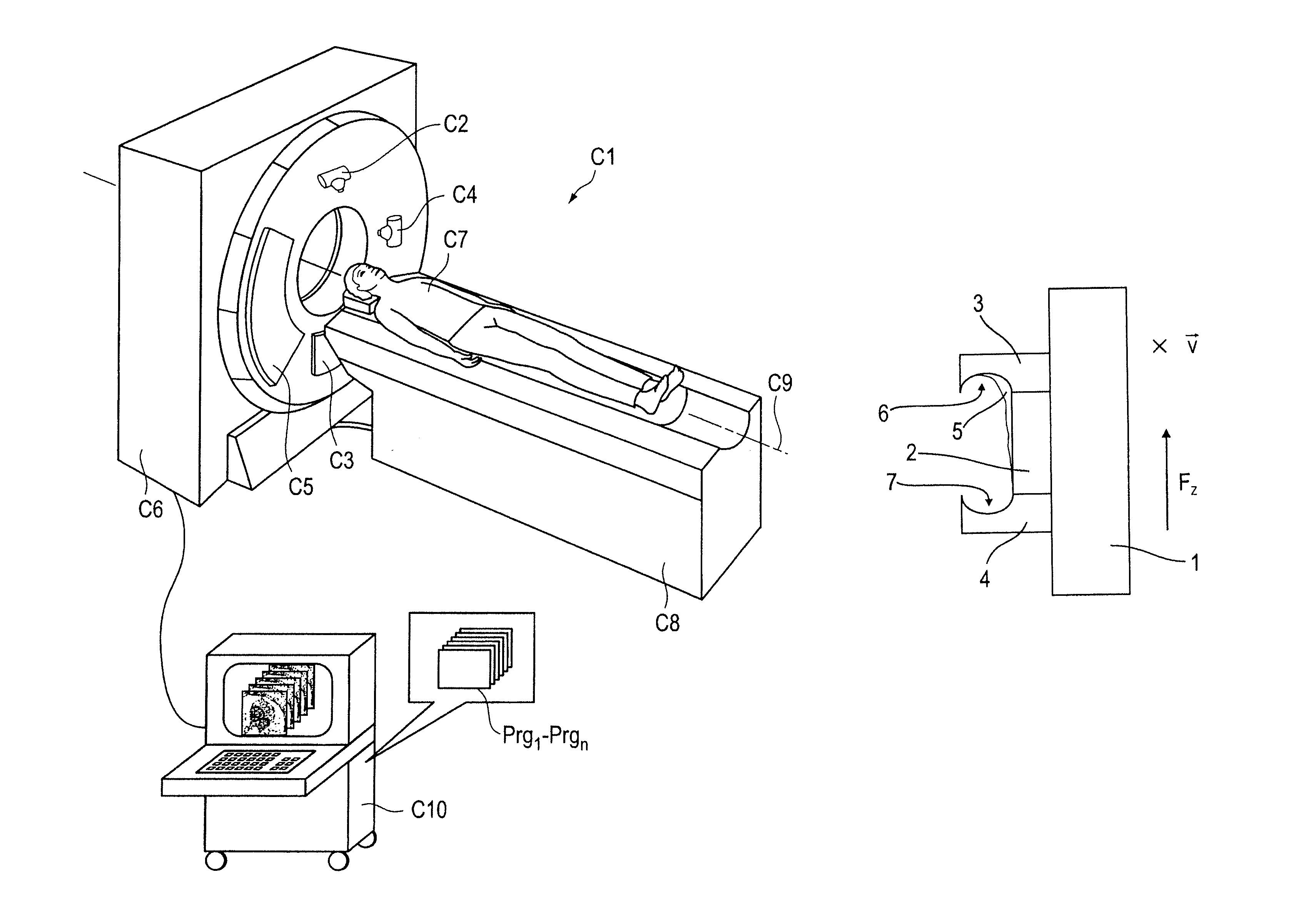
[0034]Shown by way of example in FIG. 1 is a computed tomography (CT) system C1 with a detector C3. This CT system C1 has a gantry housing C6 in which a gantry is located with an x-ray tube C2 that, together with a detector C3 situated opposite the x-ray tube C2, rotates around a system axis C9. At least one second x-ray tube C4 and a detector C5 situated opposite it can optionally be arranged on the gantry. Depending on the scanning, the sampling rate can hereby be increased, or another scan (for example a phase contrast scan) can be achieved. For scanning a patient C7 (for example) on a patient bed C8 is slid through the measurement field while the x-ray tubes C2 and C4 and the detectors C3 and C5 on the gantry rotate around the system axis C9.

[0035]The gantry contains a plate slip ring according to the invention for the transfer of the measured signals and to supply power to the x-ray sources, with a stator and a rotor that rotates around the system axis C9.

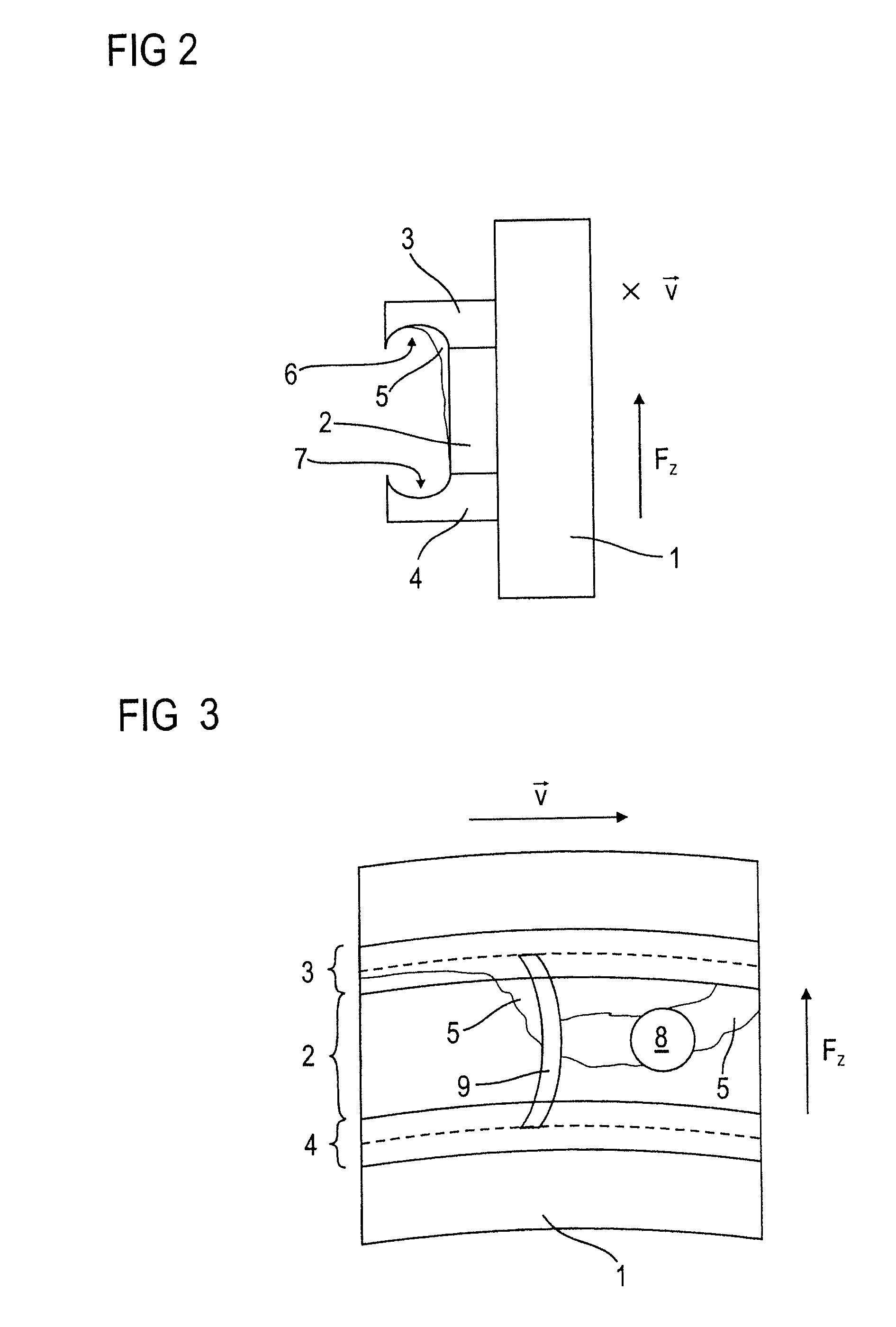
[0036]The signals dete...


PUM


Abstract

A device for the transfer of high frequency electrical signals between a rotating component and a stationary component, in particular for use in a CT system, in particular in a gantry of a CT system has a rotor, a stator; at least one brush attached at the stator, with a number of electrically conductive fibers that establish sliding contact with the rotor, and a slideway arranged to the side of the rotor and facing toward the stator. The fibers of the at least one stator-side brush rest on the slideway. A lubricant is provided on the slideway, a rotor has a capture device for the lubricant that is arranged around the outside of the slideway, and at least one return element for the captured lubricant is attached at the stator.

Description

BACKGROUND OF THE INVENTION[0001]1. Field of the Invention[0002]The present invention concerns a device to transfer high frequency electrical signals between a rotating component and a stationary component, which includes a rotor; a stator; at least one brush with a number of electrically conductive fibers attached at the stator, the fibers establishing a sliding contact with the rotor; and a slideway arranged to the side of the rotor and facing toward the stator, on which the fibers of the at least one stator-side brush rest.[0003]2. Description of the Prior Art[0004]Devices that are used to transfer high frequency electrical signals are known, such as plate slip rings that essentially represent a rotating connection. In the following, the designation “slip ring” is also used for these types of connections. These slip rings are produced in various sizes; their diameters range from a few millimeters to nearly two meters for computed tomography. Slip rings can be used, for example, t...

Claims


Application Information

Patent Timeline
Patent Type & Authority Patents(United States)
IPC IPC(8): A61B6/00
CPCA61B6/032A61B6/56A61B6/4014A61B6/4266H01R39/56
Inventor GROTTEL, JOACHIMTROELTZSCH, ANDREASWELKER, LUDWIG
Owner SIEMENS HEALTHCARE GMBH
Why Eureka
Try Eureka