Impregnated cloth

a cloth and impregnated technology, applied in the field of cloth, can solve the problems of increasing the heat input required for effective heat cutting, different properties of the edge region, and difficulty or inability to heat cut and seal, and achieve the effect of increasing the strength

Active Publication Date: 2013-01-01
CONCRETE CANVAS TECH LTD
View PDF26 Cites 16 Cited by
  • Summary
  • Abstract
  • Description
  • Claims
  • Application Information

AI Technical Summary

Benefits of technology

[0017]The elastic yarn (which will be referred to as the “edge yarn”) will normally be shorter than the self-supporting linking fibres, thereby at least partly closing off the space at the edge of the fibre but, when stretched, can have the same (or greater) length as the rest of the connecting fibres in the spacer fabric but when allowed to contract under its own tension, it achieves the desired shorter length. The elastic yarn may stretch by more than 100% of its length without breaking. This allows the same machine to be used to form the edges of the spacer fabric as is used for forming the rest of the spacer fabric; at the edge(s) of the spacer fabric, the elastic yarn can be used in place of some or all (and preferably all) of the normal linking fibre yarns with the elastic edge yarns being woven or knitted in a stretched condition. After the fabric has been removed from the machine used to make it, e.g. a knitting machine, the elasticity in the edge yarns causes the faces of the fabric to be drawn towards each other at the edge of the cloth, thereby at least partly closing the space within the fabric at its edges.
[0100]Once the cloth has set, the fibres also provide reinforcement to the set fill material and substantially increase its strength and, if the fill material becomes cracked, it allows the cloth to fail progressively (rather than catastrophically) by taking up load on the cloth.

Problems solved by technology

One problem with powder filled cloth is that the fill spills out of the open edges of the spacer fabric, causing a mess during the manufacture, transport and use of the cloth, and the loss of the fill in the edge region of the fabric makes the properties of the edge region different from those of the rest of the cloth, and often the edge region must be removed when the cloth is used.
Additionally some powdered fillers, particularly those having a melting temperature that is substantially different from the fibres of the spacer fabric, for example cement and most fillers, make heat cutting and sealing difficult or impossible for two reasons: firstly, they remain as powders and clog the melted plastic preventing it acting as a sealing material and secondly they increase the heat input required for effective heat cutting and clog the cutting blade preventing it from melting the spacer fabric fibres neatly.
However the multiple steps in the process make it time consuming and laborious or require expensive and bulky machinery, also the process is often unreliable and slow due to the requirement to have a dust free surface for effective heat sealing.
A further problem with filled cloth is that it is difficult to control the amount of liquid that is added during the setting procedure.
If the amount of liquid added is less than that required to completely set all the reactive material in the fill, some of the reactive reagent will be wasted and could have been replaced by cheaper inert filler.
Ultimately, a region may remain in the middle of the cloth that contains unset material, resulting in a significant reduction in the properties of the cloth.
Although a problem initially, if the setting liquid is water and the cloth comes into contact with water in use, e.g. because it is exposed to rain, then the reagent may become fully set in use.
On the other hand, if too much liquid is added, the consequences can be much more severe, for example the fill may be converted into a slurry and washed out of the cloth.
Also, the excess liquid will not react and instead will remain within the fill while the reagent sets; the liquid may drain out of the cloth after setting, leaving voids in the set fill, thereby reducing the density of the set material.
This can result in a high level of porosity in the final set product, which can result in a significantly lower final strength and also a lower resistance to liquid ingress, which is undesirable for applications where the cloth acts as a barrier to liquids.
Furthermore a high level of porosity can result in other undesirable properties, for example: an increase in susceptibility to freeze / thaw damage and chemical attack.
The adding of the correct amount of liquid is time-consuming and requires the use of trained personnel.

Method used


Image

  • Impregnated cloth
  • Impregnated cloth
  • Impregnated cloth

Examples


example 1

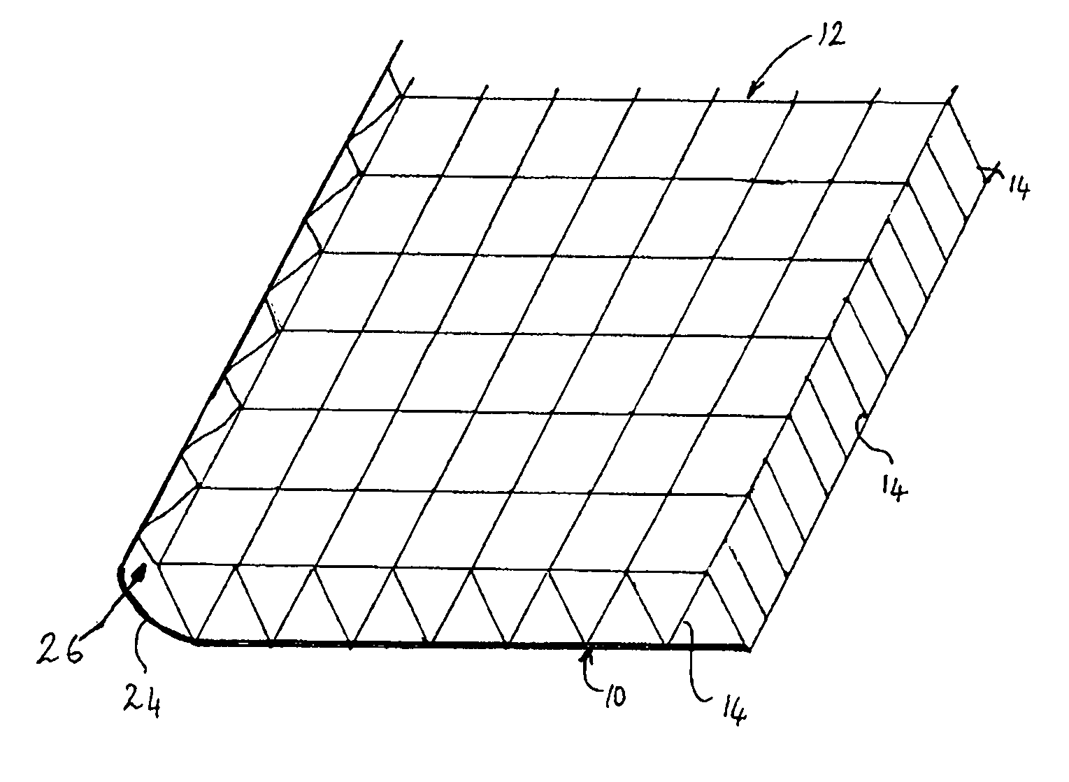
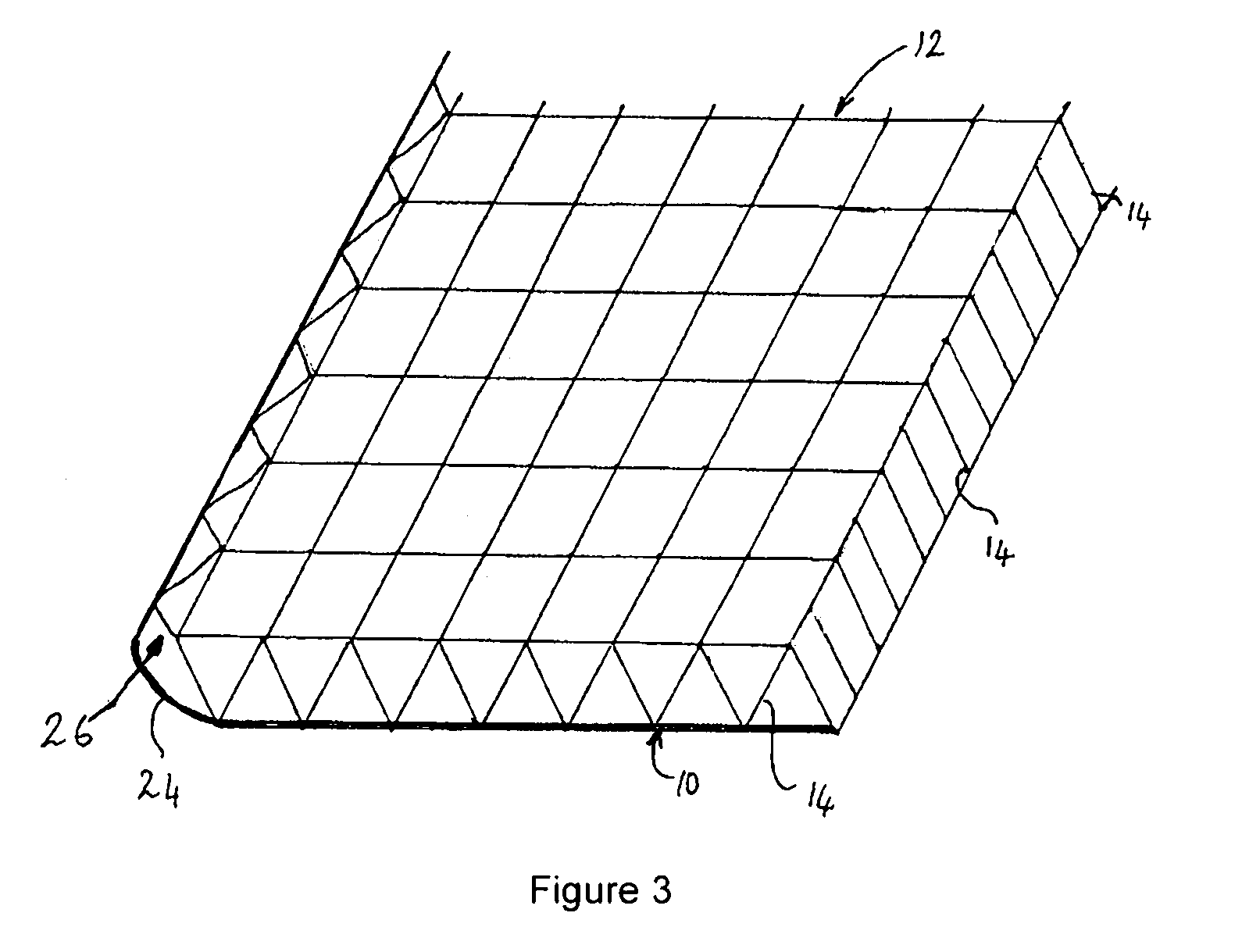
[0117]A high alumina cement is loaded into the fabric shown in FIG. 3 using the vibration and brushing techniques described above to form a filled cloth. Water is used to set the cement. The theoretical optimum water: cement ratio in this case is 0.4 by weight. The cloth has a porous face 10 of sufficiently closed construction to prevent the dry cement powder and also the cement powder once soaked in water from passing through it in significant quantities, the other face 12 has an impermeable PVC coated face to close off the pores 20. The two faces are linked by monofilament polyethylene linking fibres. The high alumina cement is compacted to give a total dry density of 1.35 g / cm3 and an average thickness of 7.3 mm between the outer surfaces of the two faces.

[0118]The linking fibres are spaced, slightly bowed and of sufficient stiffness such that after immersion in water the swelling of the cement powder between the two faces is constrained to a 14% internal volume increase. When th...


PUM

PropertyMeasurementUnit
thicknessaaaaaaaaaa
thicknessaaaaaaaaaa
thicknessaaaaaaaaaa

Abstract

A knitted spacer fabric having a tightly knitted bottom layer, a more loosely knitted upper layer and linking fibres extending across the space between the lower and upper faces. Settable material, e.g. cement, is introduced into the space between the upper and lower faces and can be caused to set by the addition of a liquid, e.g. water. Until set, the fabric is flexible and can be shaped but after the material in space has set, the fabric is rigid and can be used as a structural element in a wide range of situations. The bottom layer has an extension that extends beyond the upper face and is connected to the upper face by elastic connecting fibres that draw the extension towards the other face, thereby at least partly closing the space at the edge of the cloth and preventing the settable material from spilling out.

Description

CROSS-REFERENCE TO RELATED APPLICATION[0001]This application is the U.S. national phase of PCT application Ser. No. PCT / GB2010 / 000156 filed Jan. 29, 2010 which claims priority to European application EP09001199.0 filed Jan. 29, 2009, the disclosures of which are incorporated in their entirety by reference herein.TECHNICAL FIELD[0002]The present invention relates to a cloth that has been impregnated with a material that, when mixed with a liquid, will set, or, in one embodiment, will set when exposed to radiation. Such cloth has numerous applications.TECHNICAL BACKGROUND[0003]WO 2005 / 124063 describes a shelter that includes a ground sheet and a cover; the space between the ground sheet and the cover can be inflated by pumping air into the space to raise the cover and form the shelter. The cover is made of a fabric that has been impregnated with cement; the fabric may be a type of felt known as “wadding”, which is a loose non-woven fabric. Immediately before the interior space is infl...

Claims


Application Information

Patent Timeline
Patent Type & Authority Patents(United States)
IPC IPC(8): B32B3/02B32B5/26B32B13/14B32B3/26
CPCD04B21/14E04C5/07B32B5/26B32B13/14B05D7/24B29C53/005B32B5/06D06M11/83E02B3/12Y10T428/13D10B2403/021D10B2403/02421Y10T428/23Y10T428/232Y10T428/234Y10T428/24488B32B1/06B32B3/12B32B3/22B32B5/02Y10T428/249954Y10T428/23914Y10T428/249968Y10T442/413Y10T428/249962Y10T428/23921Y02A50/00B32B3/02B28B19/00B28B23/0006B32B5/026B32B2250/02B32B2250/20B32B2260/023B32B2260/044B32B2307/3065B32B2307/712B32B2307/7246B32B2307/7265B32B2419/00B32B2451/00B32B2556/00B32B2605/12C04B7/32C04B40/0067D06B1/12D06B3/10D06B2700/27D06M23/08D06M2200/30D10B2505/02D10B2505/12D10B2505/18E02B3/122E04B1/94E04G23/0281
Inventor CRAWFORD, WILLIAM CAMPBELLBREWIN, PETER ERIC
Owner CONCRETE CANVAS TECH LTD
Why Eureka
Try Eureka