Amplifier, optical receiver circuit, optical module and data exchange system
a technology of optical receiver circuit and optical module, which is applied in the direction of amplifiers with field-effect devices, electromagnetic transmission, electromagnetic transceivers, etc., can solve the problems of difficult circuit system to inhibit power supply noise, and achieve the effect of reducing the amount of superimposed power supply noise, reducing the noise, and reducing the nois
- Summary
- Abstract
- Description
- Claims
- Application Information
AI Technical Summary
Benefits of technology
Problems solved by technology
Method used
Image
Examples
first embodiment
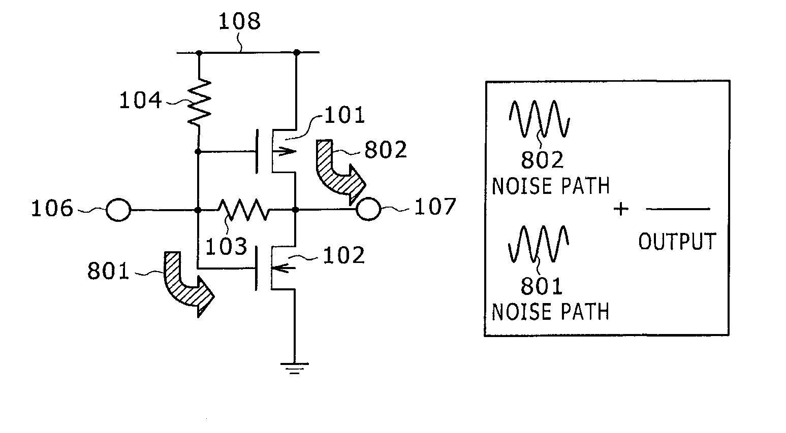
[0040]FIGS. 3A and 3B show an example of an amplifier according to a first embodiment of the present invention. FIG. 3A is a schematic circuit diagram illustrating the amplifier according to the first embodiment of the present invention. FIG. 3B is a diagram illustrating a small signal equivalent circuit that represents a signal path between an output terminal and a power supply for the amplifier shown in FIG. 3A.
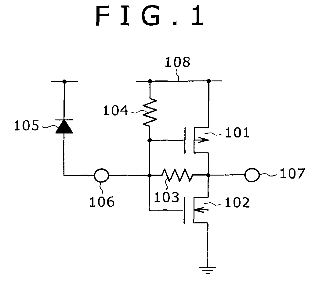
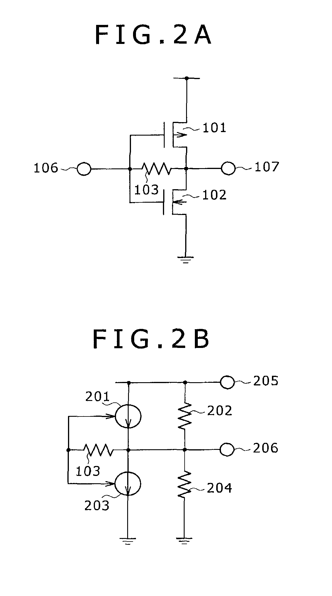
[0041]The amplifier shown in FIG. 3A includes a CMOS inverter, resistors 103, 104, an input terminal 106, an output terminal 107, and a power supply 108. The CMOS inverter includes a PMOS transistor 101 and an NMOS transistor 102. The resistor 103 is placed in a feedback path that is extended from the output terminal 107 of the CMOS inverter to the input terminal 106, and forms a shunt feedback signal amplifier. The resistor 104 is positioned between the input terminal 106 and the power supply 108. As the resistor 104 is positioned in such a manner, two paths are formed for...
second embodiment
[0051]FIG. 6 is a schematic circuit diagram illustrating an example of the amplifier according to a second embodiment of the present invention. The amplifier according to the second embodiment differs from the amplifier according to the first embodiment in that a resistor 124 for noise rejection is connected to a ground. The noise rejection resistor 124 is provided to form two noise paths that transmit ground noise to the output terminal 107. One noise path 804 transmits the ground noise to the output terminal 107 through the NMOS transistor 102. The other noise path 803 transmits the ground noise to the output terminal 107 through the resistor 124 and then the PMOS transistor 101. The noise path 804 is of a common gate type that inputs noise into the source of the NMOS transistor 102 and outputs the noise to the drain. Therefore, the phase of the ground noise is the same as the phase transmitted to the output terminal 107. On the other hand, the noise path 803 is of a common source...
third embodiment
[0052]FIGS. 7A and 7B are diagrams illustrating examples of the amplifier according to a third embodiment of the present invention. More specifically, FIGS. 7A and 7B show modifications of the amplifier according to the third embodiment of the present invention.
[0053]The configuration of the amplifier shown in FIG. 7A is characterized in that the resistor 104 shown in FIG. 3A is replaced by a variable resistor 134. The configuration of the amplifier shown in FIG. 7B is characterized in that the resistor 124 shown in FIG. 6 is replaced by a variable resistor 144. In the third embodiment, a variable resistor is used instead of a resistor. The employed variable resistor 134 or variable resistor 144 is used for noise rejection. These variable resistors 134, 144 can change the amount of superimposed noise and provide adjustability even when variation occurs in the elements in the amplifier. Further, the above-described effect can be achieved with a low-area amplifier.
PUM
 Abstract
Description
Claims
Application Information
 - R&D
- Intellectual Property
- Life Sciences
- Materials
- Tech Scout
- Unparalleled Data Quality
- Higher Quality Content
- 60% Fewer Hallucinations
Browse by: Latest US Patents, China's latest patents, Technical Efficacy Thesaurus, Application Domain, Technology Topic, Popular Technical Reports.
© 2025 PatSnap. All rights reserved.Legal|Privacy policy|Modern Slavery Act Transparency Statement|Sitemap|About US| Contact US: help@patsnap.com


