System and method for managing heave pressure from a floating rig

a floating rig and pressure management technology, applied in special purpose vessels, sealing/packing, borehole/well accessories, etc., can solve the problems of wellbore pressure fluctuation, loss of circulation or an influx of formation fluid, and depletion of reservoirs and deepwater prospects

Inactive Publication Date: 2013-01-08
WEATHERFORD TECH HLDG LLC
View PDF574 Cites 80 Cited by
  • Summary
  • Abstract
  • Description
  • Claims
  • Application Information

AI Technical Summary

Benefits of technology

[0035]A system for both conventional and MPD drilling is provided to compensate for heave induced pressure fluctuations on a floating rig when a drill string or other tubular is lifted off bottom and suspended on the rig. When suspended, the tubular moves vertically within a riser, such as when tubular connections are made during MPD, when tripping, or when a gas kick is circulated out during conventional drilling. The system may also be used to compensate for heave induced pressure fluctuations on a floating rig from a telescoping joint located below an RCD when a drill string or other tubular is rotating for drilling. The system may be used to better maintain a substantially constant BHP below an RCD or a closed annular BOP. Advantageously, a method for use of the below system is provided.

Problems solved by technology

During such operations, ocean wave heave of the rig may cause the drill string or other tubular to act like a piston moving up and down within the “pressure vessel” in the riser below the RCD, resulting in fluctuations of wellbore pressure that are in harmony with the frequency and magnitude of the rig heave.
This can cause surge and swab pressures that will effect the bottom hole pressures and may in turn lead to lost circulation or an influx of formation fluid, particularly in drilling formations with narrow drilling windows.
In benign seas of less than a few feet of wave heave, the ability of the CBHP MPD method to maintain a more constant equivalent mud weight is not substantially compromised to a point of non-commerciality.
However, there are depleted reservoirs and deepwater prospects, such as in the North Sea, offshore Brazil, and elsewhere, where the pressure fluctuation from wave heaving must be lowered to 15 psi to stay within the narrow drilling window between the fracture and the pore pressure gradients.
Otherwise, damage to the formation or a well kick or blow out may occur.
An identified disadvantage with the method is that the flow rate must be rapidly and continuously adjusted, which is described as likely to be challenging.
Otherwise, fracturing or influx is a possibility.
However, again a rapid system response is required to compensate for the rapid heave motions, which is difficult in moderate to high heave conditions and narrow drilling windows.
A disadvantage with both methods is that a rapid response is required at the fluid level interface to compensate for pressure.
Subsea mud lift systems utilizing only an adjustable mud / water or mud / air level in the riser will have difficulty controlling surge and swab effects.
Another disadvantage is the high cost of a subsea pump operation.
The authors in the above IADC / SPE 108346 technical paper conclude that given the large heave motion of the MODU (±2 to 3 m), and the short time between surge and swab pressure peaks (6 to 7 seconds), it may be difficult to achieve complete surge and swab pressure compensation with any of the proposed methods.
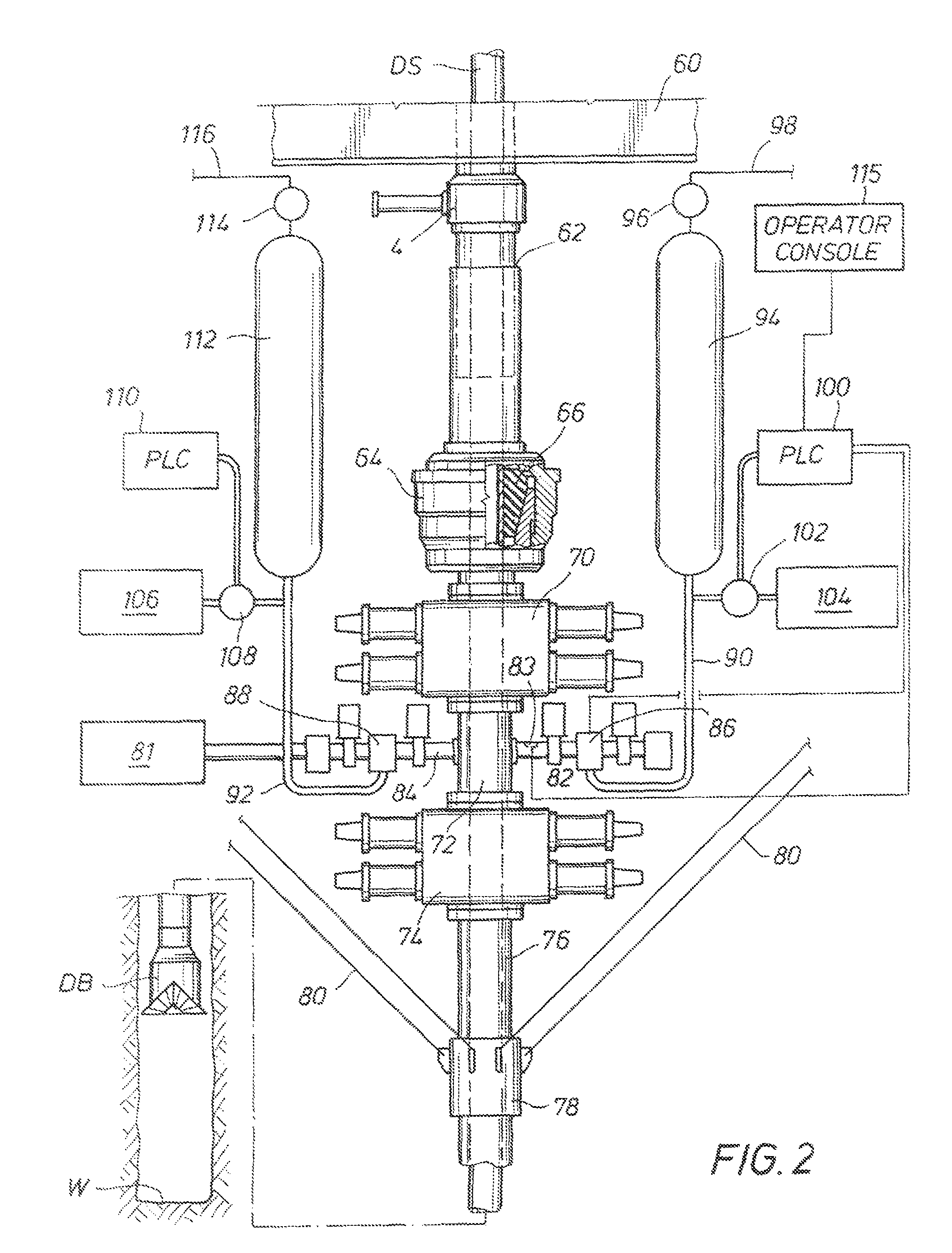
However, such a proposed solution presents a formidable task given the heave intervals of less than 30 seconds, since even programmable logic controller (PLC) controlled chokes consume that amount of time each heave direction to receive measurement while drilling (MWD) data, interpreting it, instructing a choke setting, and then reacting to it.
However, accurate measurements are difficult to obtain and then respond to, particularly in such a short time frame.
Moreover, predictive control is difficult to achieve, since rogue waves or other unusual wave conditions, such as induced by bad weather, cannot be predicted with accuracy.
Often, the result is slower than desired tripping speeds to avoid surge-swab effects.
This can create significant delays, particularly with deepwater rigs commanding rental rates of $500,000 per day.
The problem of maintaining a substantially constant pressure may also exist in certain applications of conventional drilling with a floating rig.
A surface BOP may be positioned on such a riser, resulting in lower maintenance and routine stack testing costs.
As with annular BOPs, drilling must cease when the internal ram BOP seal is closed or sealed against the drill string, or seal wear will occur.
There appears to be a general consensus that the use of deepwater floating rigs with surface BOPs and slim risers presents a higher risk of the kick coming to surface before a BOP can be closed.
Significant heaving on intervals such as 30 seconds (peak to valley and back to peak) may cause or exacerbate many time consuming problems and complications resulting therefrom, such as (1) rubble in the wellbore, (2) out of gauge wellbore, and (3) increased quantities of produced-to-surface hydrocarbons.
Wellbore stability may be compromised.
However, a bumper sub only has a maximum 5 foot (1.5 m) stroke range, and its 37 foot (11.3 m) length limits the ability to stack bumper subs in tandem or in triples for use in rough seas.
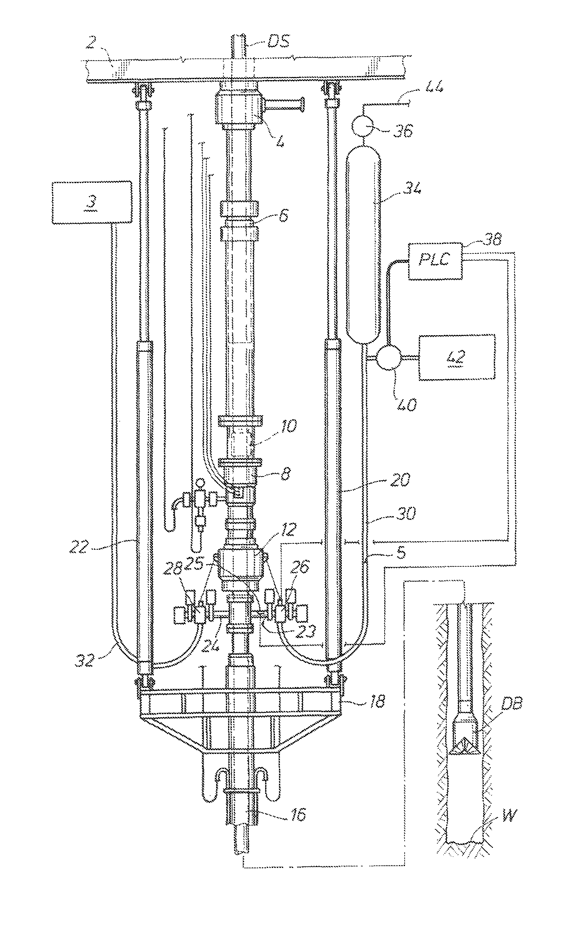
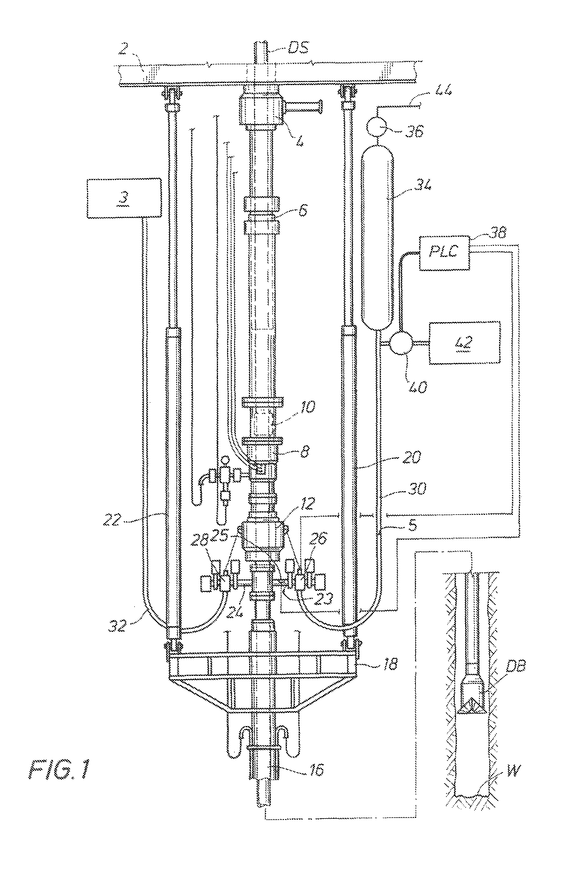
However, when a riser slip joint is located within the “pressure vessel” in the riser below the RCD, its telescoping movement may result in fluctuations of wellbore pressure much greater than 350 psi that are in harmony with the frequency and magnitude of the rig heave.
This creates problems with MPD in formations with narrow drilling windows, particularly with the CBHP variation of MPD.

Method used


Image

  • System and method for managing heave pressure from a floating rig
  • System and method for managing heave pressure from a floating rig
  • System and method for managing heave pressure from a floating rig

Examples


Embodiment Construction

[0049]The below systems and methods may be used in many different drilling environments with many different types of floating drilling rigs, including floating semi-submersible rigs, submersible rigs, drill ships, and barge rigs. The below systems and methods may be used with MPD, such as with CBHP to maintain a substantially constant BHP, during tripping including drill string connections and disconnections. The below systems and methods may also be used with other variations of MPD practiced from floating rigs, such as dual gradient drilling and pressurized mud cap. The below systems and methods may be used with conventional drilling, such as when the annular BOP is closed to circulate out a kick or riser gas, and also during the time mud density changes are being made to get the well under control, while the floating rig experiences heaving motion. The more compressible the drilling fluid, the more benefit that will be obtained from the below systems and methods when underbalance...


PUM


Abstract

A system compensates for heave induced pressure fluctuations on a floating rig when a drill string or tubular is lifted off bottom and suspended on the rig, such as when tubular connections are made during MPD, tripping, or when a kick is circulated out during conventional drilling. In one embodiment, a liquid and a gas interface moves along a flow line between a riser and a gas accumulator as the tubular moves up and down. In another embodiment, a pressure relief valve or adjustable choke allows the movement of fluid from the riser when the tubular moves down, and a pump with a pressure regulator moves fluid to the riser when the tubular moves up. In other embodiments, a piston connected with the rig or the riser telescoping joint moves in a fluid container thereby communicating fluid either into or out of the riser annulus.

Description

CROSS-REFERENCE TO RELATED APPLICATIONS N / ASTATEMENT REGARDING FEDERALLY SPONSORED RESEARCH OR DEVELOPMENT[0001]N / AREFERENCE TO MICROFICHE APPENDIX[0002]N / ABACKGROUND OF THE INVENTION[0003]1. Field of the Invention[0004]This invention relates to conventional and / or managed pressure drilling from a floating rig.[0005]2. Description of the Related Art[0006]Rotating control devices (RCDs) have been used in the drilling industry for drilling wells. An internal sealing element fixed with an internal rotatable member of the RCD seals around the outside diameter of a tubular and rotates with the tubular. The tubular may be a drill string, casing, coil tubing, or any connected oilfield component. The tubular may be run slidingly through the RCD as the tubular rotates, or when the tubular is not rotating. Examples of some proposed RCDs are shown in U.S. Pat. Nos. 5,213,158; 5,647,444 and 5,662,181.[0007]RCDs have been proposed to be positioned with marine risers. An example of a marine riser...

Claims


Application Information

Patent Timeline
Patent Type & Authority Patents(United States)
IPC IPC(8): E21B19/09E21B17/07
CPCE21B19/09E21B21/08E21B33/085E21B47/0001B63B35/4413E21B19/006E21B33/064E21B34/04E21B7/12E21B2021/006E21B21/085E21B47/001
Inventor HANNEGAN, DON M.BAILEY, THOMAS F.HARRALL, SIMON J.
Owner WEATHERFORD TECH HLDG LLC
Why Eureka
Try Eureka