Power amplifier with dynamically added supply voltages

a power amplifier and dynamic supply voltage technology, applied in the field of amplifiers, can solve the problems of difficult to achieve a flat gain versus power characteristic, difficult to tune both load impedances, and insufficient instantaneous bandwidth of the radio frequency amplifier with envelope tracking

Active Publication Date: 2013-01-15
TELEFON AB LM ERICSSON (PUBL)
View PDF8 Cites 6 Cited by
  • Summary
  • Abstract
  • Description
  • Claims
  • Application Information

AI Technical Summary

Benefits of technology

[0009]In this aspect of the present disclosure the first power source is sufficient to achieve a desired power level for the amplified radio signals at a relatively low output power compared to the maximum achievable output power. The second transistor is configured such that the second transistor provides an additional power supply to the first transistor for enabling the first transistor to generate larger signal amplitudes of the amplified signal. The power supply of the amplifier is dynamically adapted to the level of power supply that is actually needed to generate a specific output signal amplitude and thus the efficiency of the amplifier is substantially constant over a range of different output power levels. The first capacitor is a short cut for high frequency signals so that the amplified radio signals are not affected by the at least second transistor.
[0012]In another aspect of the present disclosure a second input port of the at least one second transistor is connected to a second bias level source through a second diode. The second diode protects the second transistor against base / emitter break down.
[0013]In another aspect of the present disclosure a third diode is inserted between a control input of the second transistor and the emitter of the second transistor. The third diode protects the second transistor against base / emitter break down.
[0015]In another aspect of the present disclosure a second input port of the second transistor is connected to a bias level source. By means of the bias level source the level at which the at least second transistor starts to operate is set. The bias voltage has to be chosen in dependence of the properties of the amplifier arrangement such as, but not limited to, the first supply voltage, a first forward voltage of the first diode, a second forward voltage of the second diode, a second base / emitter path of the at least second transistor. In general, a too high bias voltage will lower the efficiency as the second power source delivers power when it is not yet needed and a too low bias voltage will prevent the second power source to deliver power via the at least second transistor and will distort the output signal.

Problems solved by technology

It is difficult to tune both load impedances of the Doherty amplifier and it is further difficult to achieve a flat gain versus power characteristic.
However, the instantaneous bandwidth of the radio frequency amplifier with envelope tracking is too low and switching supply voltages create spurs.

Method used


Image

  • Power amplifier with dynamically added supply voltages
  • Power amplifier with dynamically added supply voltages
  • Power amplifier with dynamically added supply voltages

Examples


Embodiment Construction

[0028]The invention will now be described on the basis of the drawings. It will be understood that the embodiments and aspects of the invention described herein are only examples and do not limit the protective scope of the claims in any way. The invention is defined by the claims and their equivalents. It will be understood that features of one aspect or embodiment of the invention can be combined with a feature of a different aspect or aspects and / or embodiments of the invention.

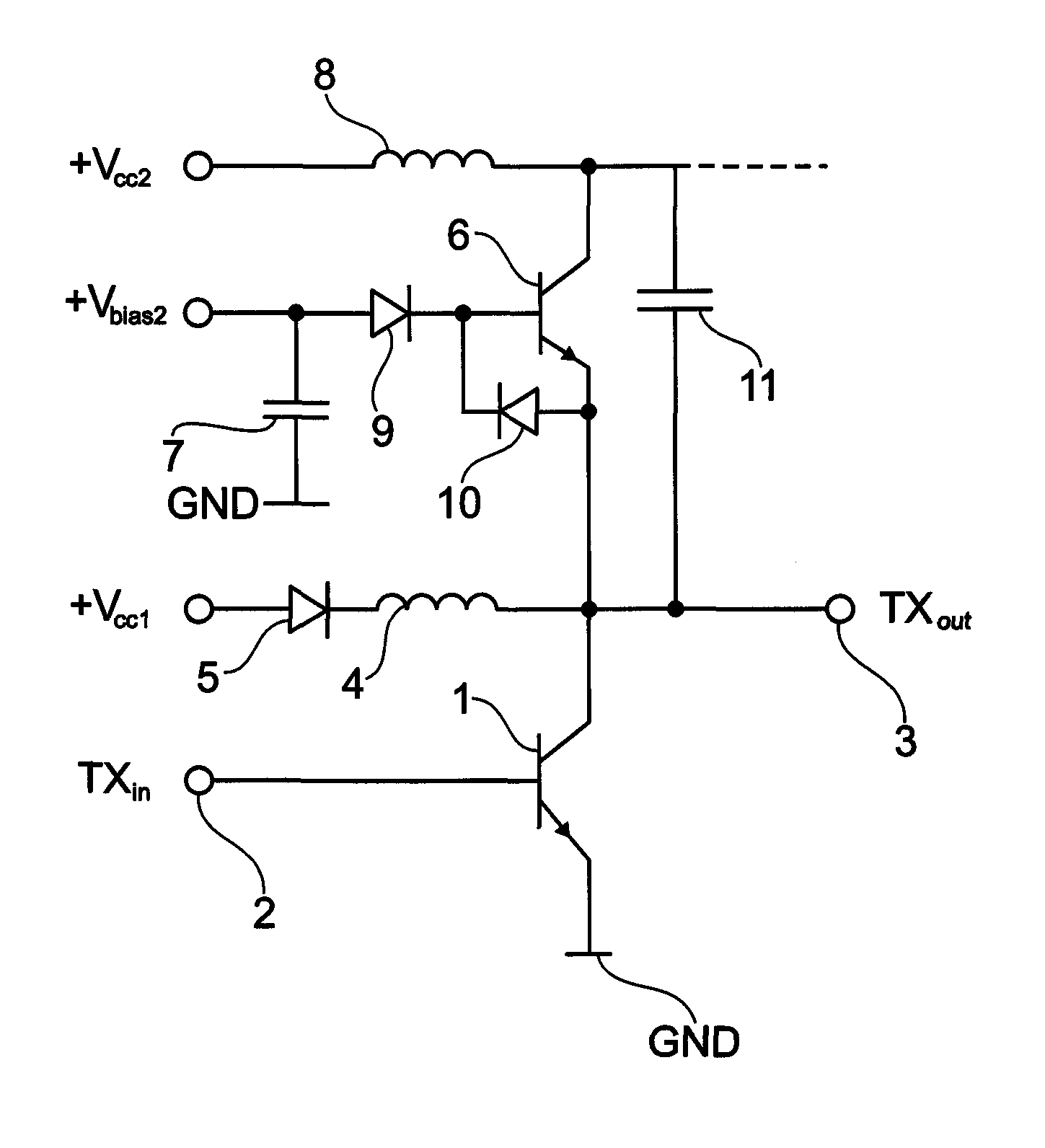
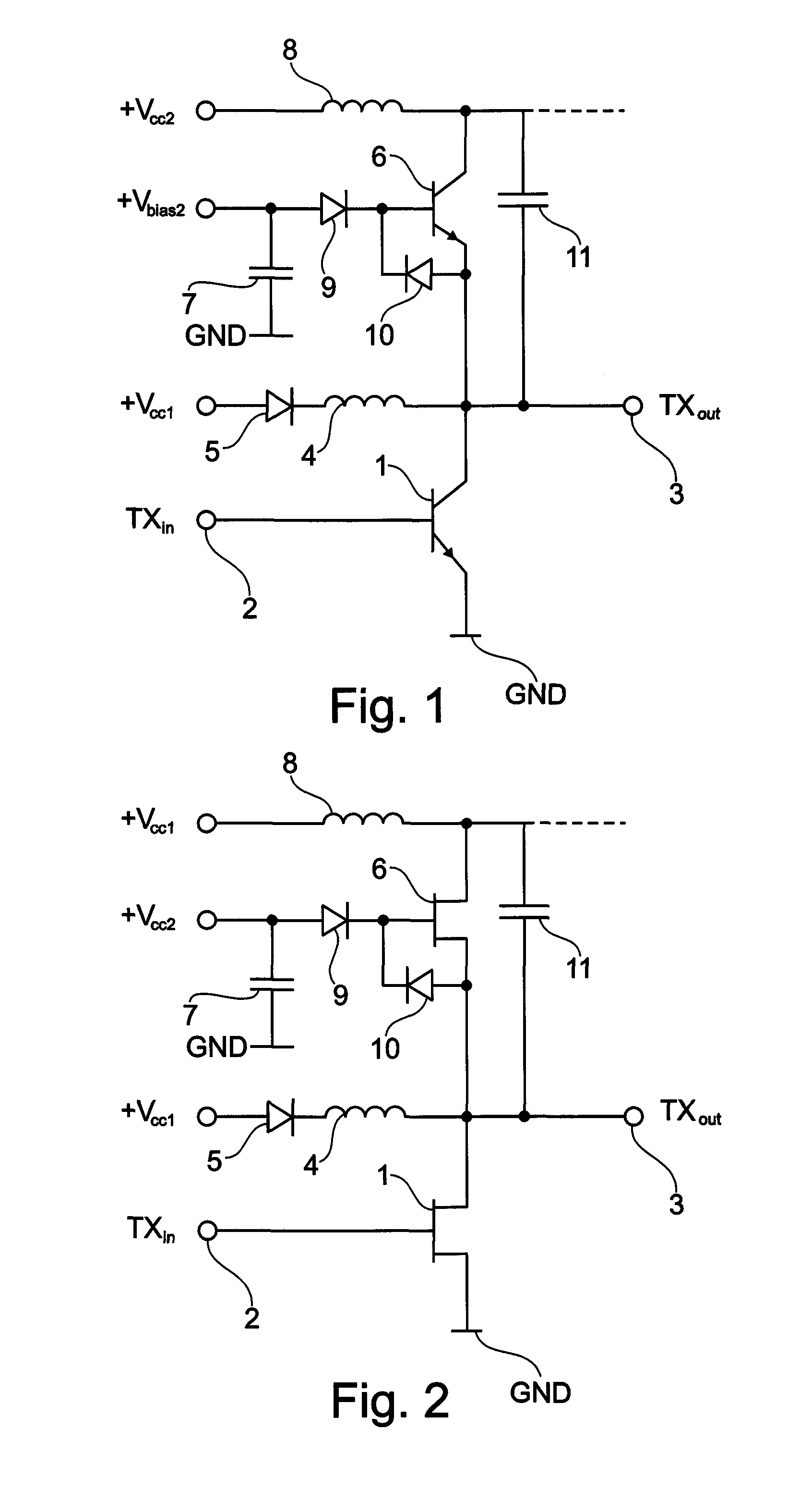
[0029]FIG. 1 shows an amplifier arrangement for a power amplifier in a radio station. The term “radio station” in intended to cover but is not limited to any stationary radio station such as a so-called base transceiver station in for example a GSM, UMTS or LTE system but also a mobile station, such as a cell phone. The term radio station shall also embrace other applications of radio equipment emitting electromagnetic waves, such as radar equipment or wireless LAN equipment. The amplifier arrangement comp...


PUM

PropertyMeasurementUnit
supply voltageaaaaaaaaaa

Abstract

An amplifier for amplifying a radio signal to a defined power output level is presented, wherein the amplifier comprises an amplifier input port, an amplifier output port, a first transistor for amplifying the radio signal received at a first transistor control input, wherein a first transistor output of the first transistor is supplied by a first power source; a at least second transistor for supplying the first transistor from a at least second power supply source. The at least second power supply source is added by the at least second transistor as a function of the power output level of the amplifier.

Description

CROSS-REFERENCE TO RELATED APPLICATIONS[0001]NoneFIELD OF THE INVENTION[0002]The field of the present disclosure relates in general to an amplifier for amplifying a radio signal used in a mobile communication network and in particular to the power supply of such an amplifier. The field of the invention further relates to a method for amplifying radio signals. The field of the application further relates to a method of manufacturing an amplifier for amplifying a radio signal. The field of the application further relates to a computer program product comprising for causing a computer to manufacture an amplifier for amplifying a radio signal.BACKGROUND OF THE INVENTION[0003]It is a general requirement to design a radio frequency power amplifier such that the radio frequency power amplifier is highly efficient and is substantially insensitive to load impedance variation and component variation or mismatching load impedances. Power efficiency, for example, is expressed as the power added...

Claims


Application Information

Patent Timeline
Patent Type & Authority Patents(United States)
IPC IPC(8): H03F3/04
CPCH03F1/0233H03F1/0255Y10T29/49016H03F2200/511H03F2200/507
Inventor KARTHAUS, UDO
Owner TELEFON AB LM ERICSSON (PUBL)
Why Eureka
Try Eureka