
Zinc oxide film forming method and apparatus

a zinc oxide film and forming method technology, applied in the direction of electrolytic capacitors, liquid/solution decomposition chemical coatings, coatings, etc., can solve the problems of low productivity of dye-sensitive solar cells in the document 1 technology, zinc oxide film falling off from the substrate, etc., to achieve superior adhesion to the conductive layer and easy and efficient formation of porous zinc oxide films

Inactive Publication Date: 2013-01-29
DAINIPPON SCREEN MTG CO LTD
View PDF15 Cites 6 Cited by
  • Summary
  • Abstract
  • Description
  • Claims
  • Application Information

AI Technical Summary

Benefits of technology

[0007]The present invention is intended for a zinc oxide film forming method of forming a porous zinc oxide film on a base member, the zinc oxide film being used as a photoelectric conversion layer in a dye-sensitized solar cell. It is an object of the present invention to easily and efficiently form the porous zinc oxide film which has superior adhesion to the conductive layer of the base member.
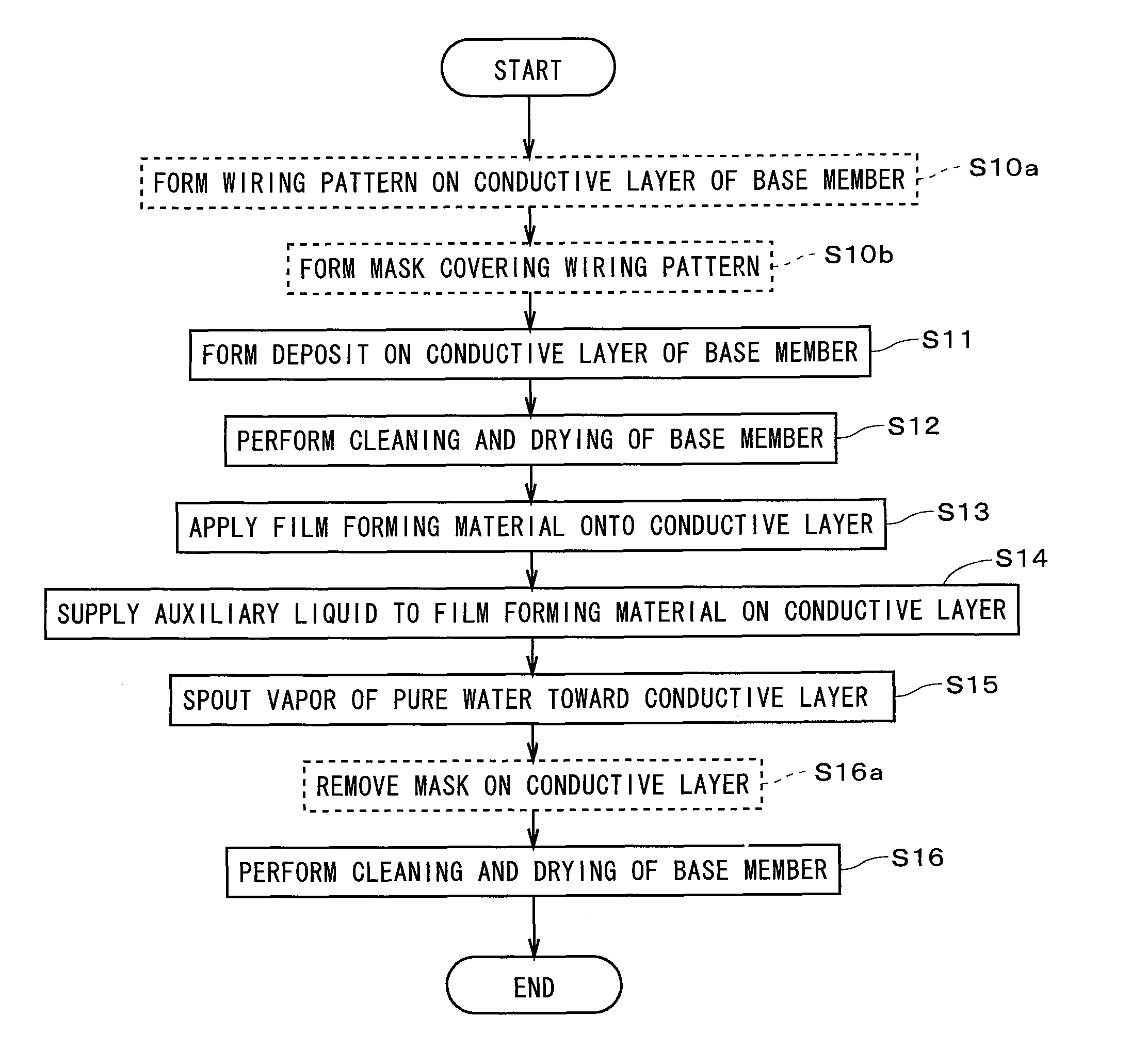
[0008]The zinc oxide film forming method according to the present invention comprises the steps of: a) forming a deposit on a conductive layer formed on a base member by electrodeposition or chemical deposition, the deposit containing zinc oxide; and b) applying film forming material which is in liquid or paste form and contains particles of zinc oxide and solvent, onto the conductive layer where the deposit is formed, and removing the solvent from film forming material on the conductive layer to form a porous zinc oxide film on the conductive layer. In the present invention, it is possible to easily and efficiently form the porous zinc oxide film which has superior adhesion to the conductive layer of the base member.
[0009]According to a preferred embodiment of the present invention, the step b) comprises the step of supplying auxiliary liquid to film forming material on the conductive layer after application of film forming material, the auxiliary liquid being pure water or containing zinc ion. It is therefore possible to further strengthen the bonds between the particles of zinc oxide and the bonds between the particles and the deposit.
[0010]According to another preferred embodiment of the present invention, since the method further comprises the step of adding metal to the zinc oxide film by supplying the zinc oxide film with solution containing ion of the metal which is nobler than zinc after the step b), the zinc oxide film to which another kind of metal is added can be formed easily.
[0011]According to still another preferred embodiment of the present invention, a wiring pattern made of material whose specific resistance is lower than that of the conductive layer is formed on the conductive layer, and a mask having repellency to film forming material is formed so that the wiring pattern is covered with the mask in the base member. This suppresses that the film forming material adheres to the mask, and it is therefore possible to remove the mask easily.
[0012]In the case where the deposit is formed in the form of numerous islands in the step a), formation of the deposit can be performed in a short time period. In the case where the deposit is formed in the form of a film in the step a), adhesion between the zinc oxide film and the conductive layer can be further increased.

Problems solved by technology

However, there is a problem that productivity of the dye-sensitized solar cell in the technique of the Document 1 becomes low, because long process time is required for electrodeposition of the zinc oxide film and desorption of the template agent.
As the result, there is a case where the zinc oxide film falls off from the substrate in the downstream processes of manufacturing of dye-sensitized solar cell.

Method used


Image

  • Zinc oxide film forming method and apparatus
  • Zinc oxide film forming method and apparatus
  • Zinc oxide film forming method and apparatus

Examples


Embodiment Construction

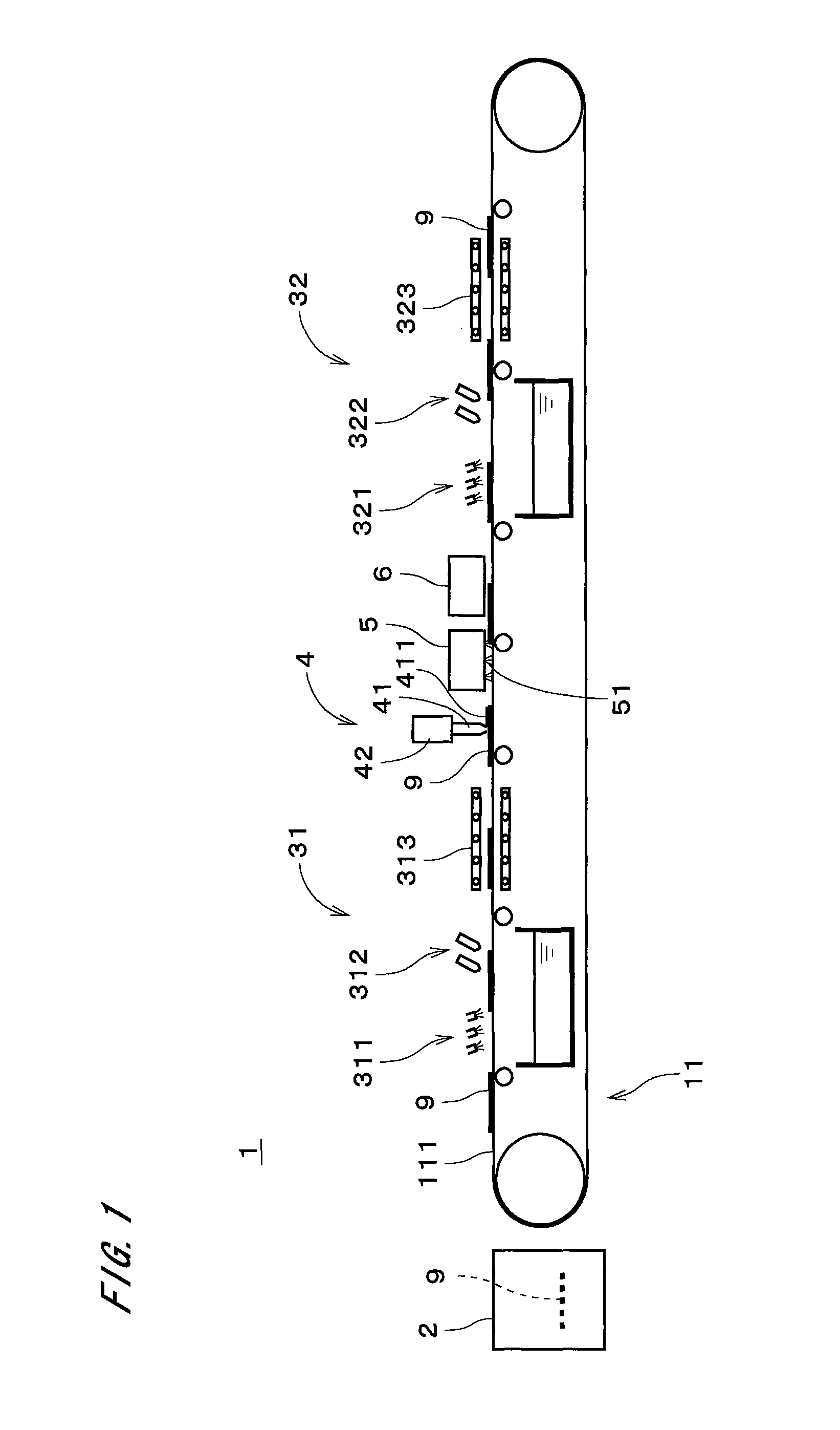
[0025]FIG. 1 is a view showing a constitution of a zinc oxide film forming apparatus 1 in accordance with a first preferred embodiment of the present invention. The zinc oxide film forming apparatus 1 is used for forming a porous thin film of zinc oxide on a transparent resin substrate 9 which has a transparent conductive layer such as ITO (Indium Tin Oxide) film or FTO (Fluorine-doped Tin Oxide) film. In the downstream processes, a counter substrate having a counter electrode (a counter electrode conductive layer) is provided so that the counter substrate faces the resin substrate 9 on which the zinc oxide film is formed, liquid electrolyte is injected between two substrate to form a charge transport layer (electrolyte layer), and therefore the dye-sensitized solar cell is manufactured. As above, the zinc oxide film formed in zinc oxide film forming apparatus 1 is used as a photoelectric conversion layer (it is also called as photoelectrode layer) in the dye-sensitized solar cell.

[...


PUM

PropertyMeasurementUnit
flow rateaaaaaaaaaa
temperatureaaaaaaaaaa
electrical potentialaaaaaaaaaa

Abstract

In the zinc oxide film forming apparatus (1), the deposit containing zinc oxide is formed on the conductive layer of the resin substrate (9) by electrodeposition in the deposition part (2), and the resin substrate (9) is carried to the applying part (4). Subsequently, the film forming material which is in liquid or paste form and contains particles of zinc oxide and solvent is applied onto the conductive layer, and then the solvent is removed from the film forming material on the conductive layer by volatilization. It is therefore possible to easily and efficiently form the porous zinc oxide film which has superior adhesion to the conductive layer of the resin substrate (9).

Description

TECHNICAL FIELD[0001]The present invention relates to a technique of forming a porous zinc oxide film on a base member, which is a film used as a photoelectric conversion layer in a dye-sensitized solar cell.BACKGROUND ART[0002]Recently, a dye-sensitized solar cell have been paid attention to and it can be used as a power source of a various product without impact to its design and be manufactured with low cost. The dye-sensitized solar cell has a structure where a transparent substrate having a conductive layer (for instance, a layer of ITO (Indium Tin Oxide) film or FTO (Fluorine-doped Tin Oxide) film), a photoelectric conversion layer, a charge transport layer, and a counter substrate having a counter electrode conductive layer are build up. The technique where paste containing semiconductive particles such as titanium oxide is applied on the substrate and the paste is burned at a high temperature, is employed as a technique of forming a porous semiconductive layer which becomes ...

Claims


Application Information

Patent Timeline
Patent Type & Authority Patents(United States)
IPC IPC(8): H01L27/142H01L21/288
CPCC23C18/1262C23C18/54C25D3/22H01G9/204H01G9/2059Y02E10/542
Inventor YANE, TAKESHI
Owner DAINIPPON SCREEN MTG CO LTD
Learn More