
Implantable flow connector

a technology of flow connectors and connectors, applied in the field of implantable medical devices, can solve the problems of reducing affecting the perfusion of the tissue, and affecting the perfusion efficiency of the tissue, so as to reduce the size of the flange

Active Publication Date: 2013-02-05
BIOCONNECT SYST
View PDF201 Cites 41 Cited by
  • Summary
  • Abstract
  • Description
  • Claims
  • Application Information

AI Technical Summary

Benefits of technology

This patent describes a method for connecting two parts of a fluidic system using a flow connector. The flow connector has a conduit with retention elements and a flange that can be expanded after insertion through an opening in a source body space. This method allows for easy and secure connection of the two parts of the system without the need for additional surgical intervention.

Problems solved by technology

This may result in restricted blood flow which may compromise perfusion to the tissue served by the blood flow.
In the case of an occluded coronary vessel, for example, an area of the heart's myocardium would be compromised, which may lead to a myocardial infarction or other ischemic heart syndrome such as congestive heart failure.
Patency may be compromised due to technical, biomechanical or pathophysiological causes.
Among the technical and biomechanical causes for compromised patency are poorly achieved anastomoses due to, for example, poor technique, trauma, thrombosis, intimal hyperplasia or adverse biological responses to the anastomosis.
Improperly anastomosed vessels may lead to leakage, create thrombus and / or lead to further stenosis at the communication site, possibly requiring re-operation or further intervention.
In addition to creating a surgical field in which it is difficult to see, leakage of fluid from the anastomosis can cause serious acute or chronic complications, which may be fatal.
In addition to the inherent inconsistencies in suture tightness, incision length, placement of the suture, stitch size, and reproducibility, suturing an anastomosis can be very time consuming.
This difficulty is compounded by the relatively small dimensions of the vessels involved or the diseased state of the vessel when creating an AV fistula.

Method used


Image

  • Implantable flow connector
  • Implantable flow connector
  • Implantable flow connector

Examples


Embodiment Construction

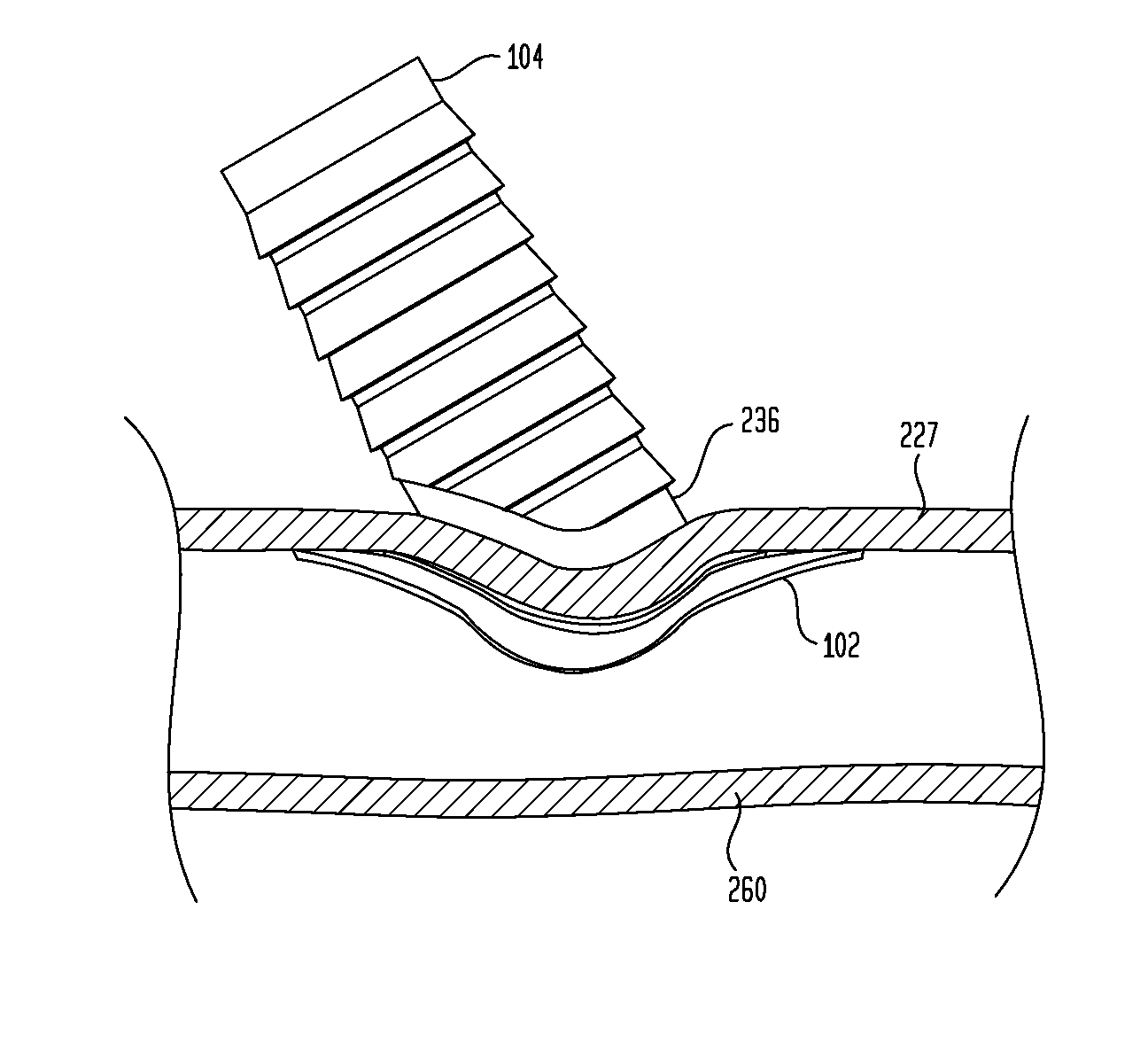
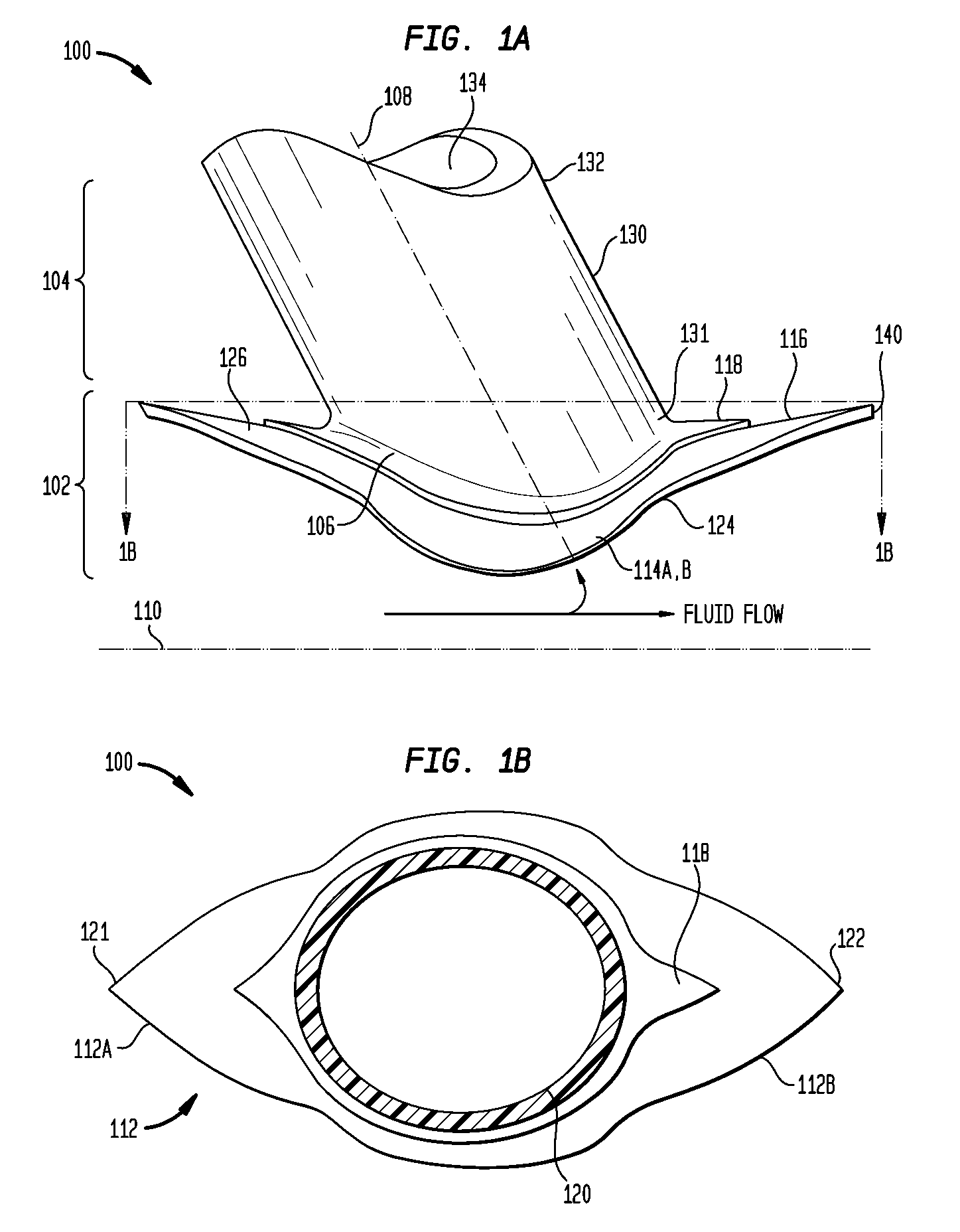
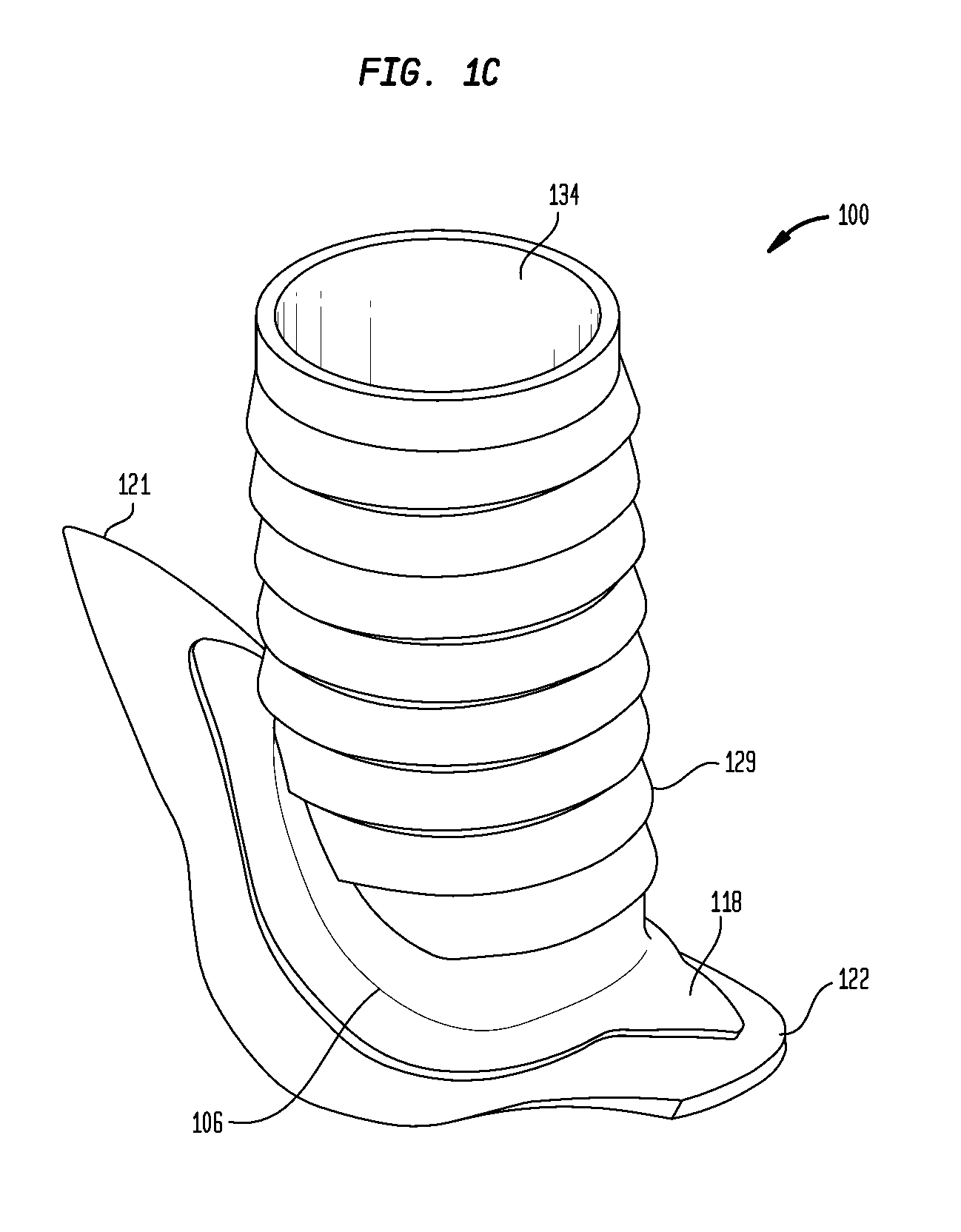
[0074]Aspects of the present invention are generally directed to an implantable flow connector, elements of an implantable flow connector and methods for manufacturing and utilizing embodiments of a flow connector. Embodiments of the flow connector of the present invention are configured to be implanted in a tissue-enclosed body space such as a body conduit or body reservoir to provide a flow path for fluid from the source body space to another body space, a man-made or body conduit, an external or implanted medical device, or other destination element.

[0075]Embodiments of the flow connector comprise a conduit having a lumen that terminates at an orifice on opposing ends of the conduit, and a flange radially extending from one of the two ends of the conduit. The flow connector is configured to be implanted into the source body space via a natural or artificial opening (e.g., a man-made opening) in a region of the tissue wall that defines the body space. The flange surrounds the cond...


PUM


Abstract

An implantable flow connector for fluidically coupling a source tissue-enclosed body space with a destination element, comprising: a conduit having a lumen terminating at an orifice at a first end of the conduit implantable in the source body space through an opening formed in a tissue wall of the source body space, and a second end of the conduit implantable in the destination element through an opening in a surface of the destination element; and a circumferential flange, radially extending from the conduit proximate the conduit first end, configured to be implanted in the source body space adjacent an opening in the tissue wall of the source body space such that the conduit extends through the opening, the flange comprising one or more circumferentially adjacent sections at least one of which has a rigidity that decreases in a radially-increasing direction.

Description

CROSS-REFERENCE TO RELATED APPLICATIONS[0001]This application claims the benefit of U.S. Provisional Application No. 60 / 953,570, entitled “Device for Interconnecting Internal Passageways in a Patient,” filed Aug. 2, 2007. This application is hereby incorporated by reference herein.BACKGROUND[0002]1. Field of the Invention[0003]The present invention relates generally to implantable medical devices and, more particularly, to implantable flow connectors.[0004]2. Related Art[0005]The mammalian body has numerous tissue-enclosed body spaces. For example, body conduits such as blood vessels, lymph and tear ducts, bowels, urethra, etc., which have a lumen through which fluid is carried to facilitate circulation, excretion or other fluid transfer function. Tissue-enclosed body spaces also include body reservoirs such as the stomach, bladder, gall bladder, lymph nodes, etc., which temporarily or permanently retain fluid.[0006]It is often necessary or desirable to directly or indirectly connec...

Claims


Application Information

Patent Timeline
Patent Type & Authority Patents(United States)
IPC IPC(8): A61M5/00A61M5/32
CPCA61B17/11A61M39/10A61M27/002A61B17/12009A61B2017/1135A61B2017/1107
Inventor DAKIN, ADAMDUGERY, MICHAELPOLK, TODDBRIGANTI, RICHARDPARIS, MICHAELGATELY, NICHOLASWIN, ZAW N.
Owner BIOCONNECT SYST
Learn More