Micro-aeration of sulfide removal from biogas

a technology of biogas and sulfide, which is applied in the field of removal of sulfide, can solve the problems of reducing the yield of methane, reducing the quality of methane as a renewable energy, and not only causing harm

Inactive Publication Date: 2013-02-05
IOWA STATE UNIV RES FOUND
View PDF16 Cites 22 Cited by
  • Summary
  • Abstract
  • Description
  • Claims
  • Application Information

AI Technical Summary

Problems solved by technology

The high sulfide level in the biogas stream is not only detrimental to many novel metal catalysts employed in thermo-catalytic processes, but also reduces the quality of methane as a renewable energy.
Moreover, aqueous sulfide in the bioreactor inhibits methanogenesis, the main pathway for methane production in anaerobic processes, which in turn significantly reduces the yield of methane.
The hydrogen sulfide in biogas limits the usage of biogas in many downstream processes.
Besides hydrogen sulfide in off-gas, if sulfides in liquid are released to receiving steams, they are toxic to aquatic life and deplete oxygen concentration.
However, the dosage of the oxidizing agents can be problematic since not only do the agents oxidize sulfide, but also other organic and inorganic compounds present in wastewater.
Thus, the addition of chlorine or nitrite to wastewater produces unwanted byproducts such as carcinogenic trihalomethane (THM), NOx, and ammonia.
However, these processes are high-cost, and provide a chemical disposal problem.
The sulfide removal activity is deteriorated over a short period of time unless the absorbents are replaced, resulting in recurring expenses.
In addition, the precipitates formed may greatly reduce the active volume of the digester.
The use of packed media in anaerobic digester or in sulfide oxidizing reactors prevents them from being useful in treating high-solids waste due to the potential of clogging.

Method used


Image

  • Micro-aeration of sulfide removal from biogas
  • Micro-aeration of sulfide removal from biogas
  • Micro-aeration of sulfide removal from biogas

Examples


example 1

Preferred Sulfide Removal Apparatus

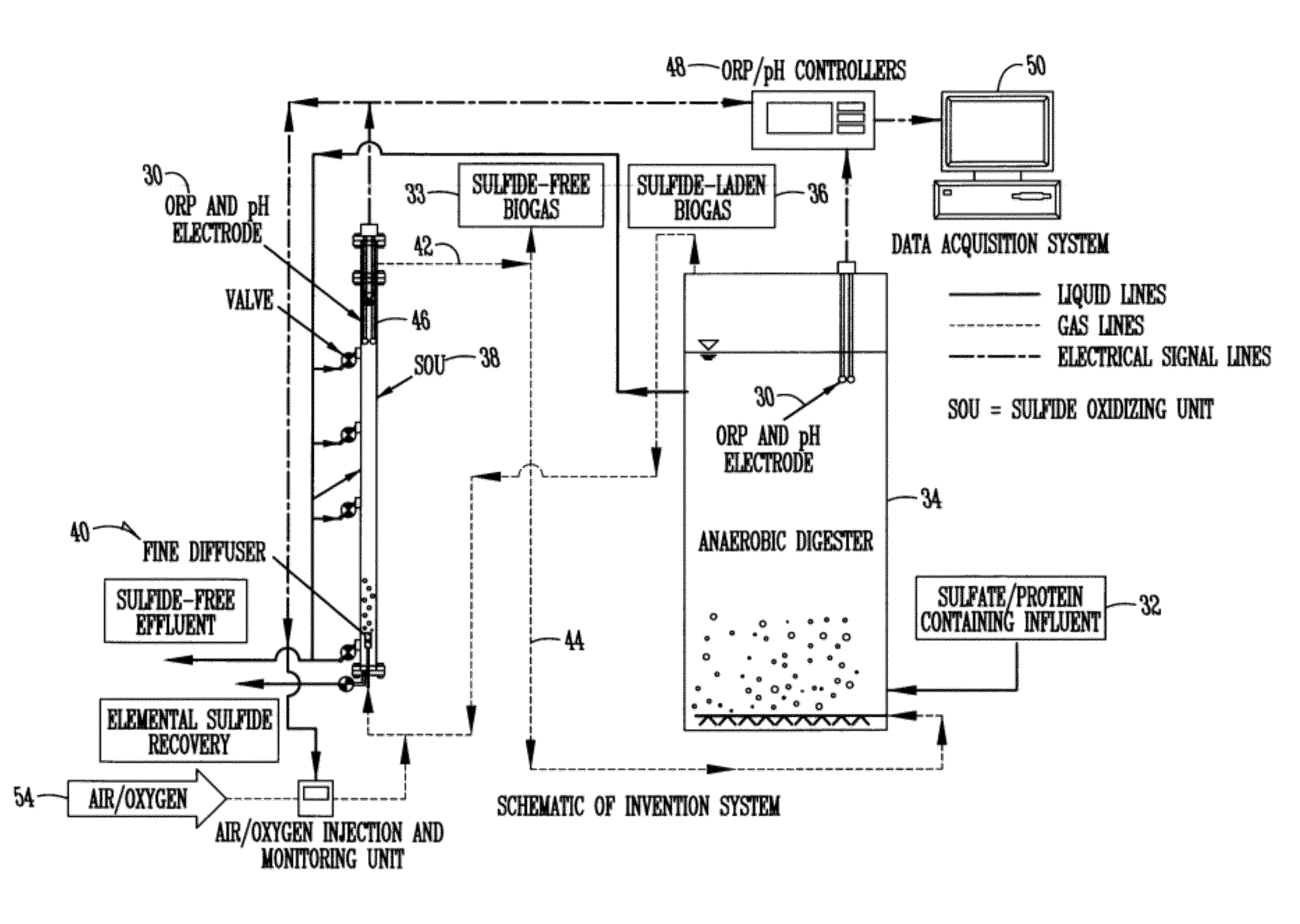
[0053]A preferred apparatus of the invention is illustrated in FIG. 3. The set-up mainly consists of two gas recirculation loops (FIG. 3). In the first loop, sulfide-laden biogas 32 bubbles at the rate of 0.05 to 5 L-biogas / Lcolumn-min through a long slender column (SOU—Sulfide Oxidizing Unit) containing liquids. In the second loop, sulfide-free biogas 33 from SOU bubbles through the sulfide producing bioreactor at the rate of 0.0015 to 0.15 L-biogas / Lbioreactor-min. The two loops are connected to each other as shown in FIG. 3.

[0054]The SOU consists of a diffuser 40 at the bottom with liquid and / or gas inlets and / or outlets along the column wall. A small chamber is located at the bottom of the SOU below the diffuser to collect elemental sulfur 52, as well as other particulate matters. The column is also equipped with air / oxygen injection 54 and monitoring unit to inject air / oxygen at the rate of 0.1 to 50% of the amount of biogas that is normally p...

example 2

A Pilot-Scale Study of Micro-Aeration for Sulfide Removal in Anaerobic Treatment of High-Solid Wastewater

[0061]The pilot-scale facility consisted of a one-liter sulfide oxidizing unit (SOU) integrated with an anaerobic digester, a continuous stirred tank reactor (CSTR) with an internal settling zone with a working volume of 92 L. The effluent from the digester was pumped out of the system into the SOU to provide medium for sulfide removal.

[0062]Sulfide-laden biogas produced in the digester was mixed with small amount of air before being forced through a diffuser located at the bottom of the SOU. In the SOU, sulfide and oxygen flowed upward in a countercurrent direction against the digester effluent, where the formation of elemental sulfur took place. The elemental sulfur produced was collected in the bottom of the SOU and discharged periodically. Sulfide-free biogas was re-circulated back to the digester to scavenge the newly formed sulfide and brought back to SOU again. The cycle w...


PUM

PropertyMeasurementUnit
heightaaaaaaaaaa
air flow rateaaaaaaaaaa
heightaaaaaaaaaa

Abstract

A novel method for treating sulfide-containing wastewater is described which involves treating sulfide-laden biogas produced in a bioreactor in a sulfide oxidizing unit (SOU). Oxidation in the SOU is monitored by an oxidation reduction potential (ORP) probe which minimizes the input of air / oxygen to produce elemental sulfur without significant production of sulfate.

Description

CROSS-REFERENCE TO RELATED APPLICATIONS[0001]This application claims priority under 35 U.S.C. §119 of a provisional application Ser. No. 61 / 103,775 filed Oct. 8, 2008, which application is hereby incorporated by reference in its entirety.GRANT REFERENCE CLAUSE[0002]This invention was funded at least in part by the USDA Contract No. 2002-34188-12035. The government may have certain rights in this invention.FIELD OF THE INVENTION[0003]This invention relates to the removal of sulfide from biogas, wastewater and other liquid streams.BACKGROUND OF THE INVENTION[0004]In recent years especially, governmental regulators have provided stringent parameters for controlling environmental pollution. The typical parameters for monitoring such pollution and the efficiency of any treatment system are COD (chemical oxygen demand) and BOD (biochemical oxygen demand). Anaerobic processing has been widely adopted to stabilize wastes / wastewater due to its several inherent merits, such as generation of r...

Claims


Application Information

Patent Timeline
Patent Type & Authority Patents(United States)
IPC IPC(8): C02F3/28B01D53/52
CPCC02F3/006C12M47/18B01D53/346B01D53/52B01D53/84C01B17/05C02F3/2893C02F2101/101C02F2209/001C02F2209/003C02F2209/04C02F2209/06C02F2209/08C02F2209/225B01D2251/102B01D2251/95B01D2256/245B01D2257/304B01D2258/05Y02E50/343Y02E50/30Y02W10/10Y02A50/20
Inventor SUNG, SHIHWUKHANAL, SAMIR KUMARDUANGMANEE, THANAPONG
Owner IOWA STATE UNIV RES FOUND
Why Eureka
Try Eureka