Austenitic ductile cast iron

a technology of ductile cast iron and cast iron, which is applied in the direction of machines/engines, stators, liquid fuel engines, etc., can solve the problems of nickel being an expensive raw material, affecting the performance of the engine, so as to achieve high strength, reduce cost, and improve the effect of performan

Active Publication Date: 2013-02-12
GARRETT TRANSPORATION I INC
View PDF12 Cites 15 Cited by
  • Summary
  • Abstract
  • Description
  • Claims
  • Application Information

AI Technical Summary

Benefits of technology

[0007]The present invention provides alloy compositions useful for preparing articles having high performance properties, particularly high strength and heat resistance. The alloys of the invention are particularly useful in that they can be prepared using lower cost materials than presently known austenitic ductile cast irons. The inventive alloys disclosed herein are particularly austenitic ductile cast iron iron-based alloys that comprise a specific elemental make-up designed to retain the noted preferred properties but with a lowered preparation cost.

Problems solved by technology

These latter elements may be intentionally added or may be present as unavoidable impurities.
These increases put a greater strain on structural engine components due to the increased temperature of exhaust gases that must pass through them.
The increased temperatures at which engine components must operate has resulted in a more limited range of materials that can be used to construct such engine components.
Nickel is an expensive raw material and suffers from a large fluctuation in price, which has become increasingly volatile.
The high cost of nickel directly impacts the cost of the end product.
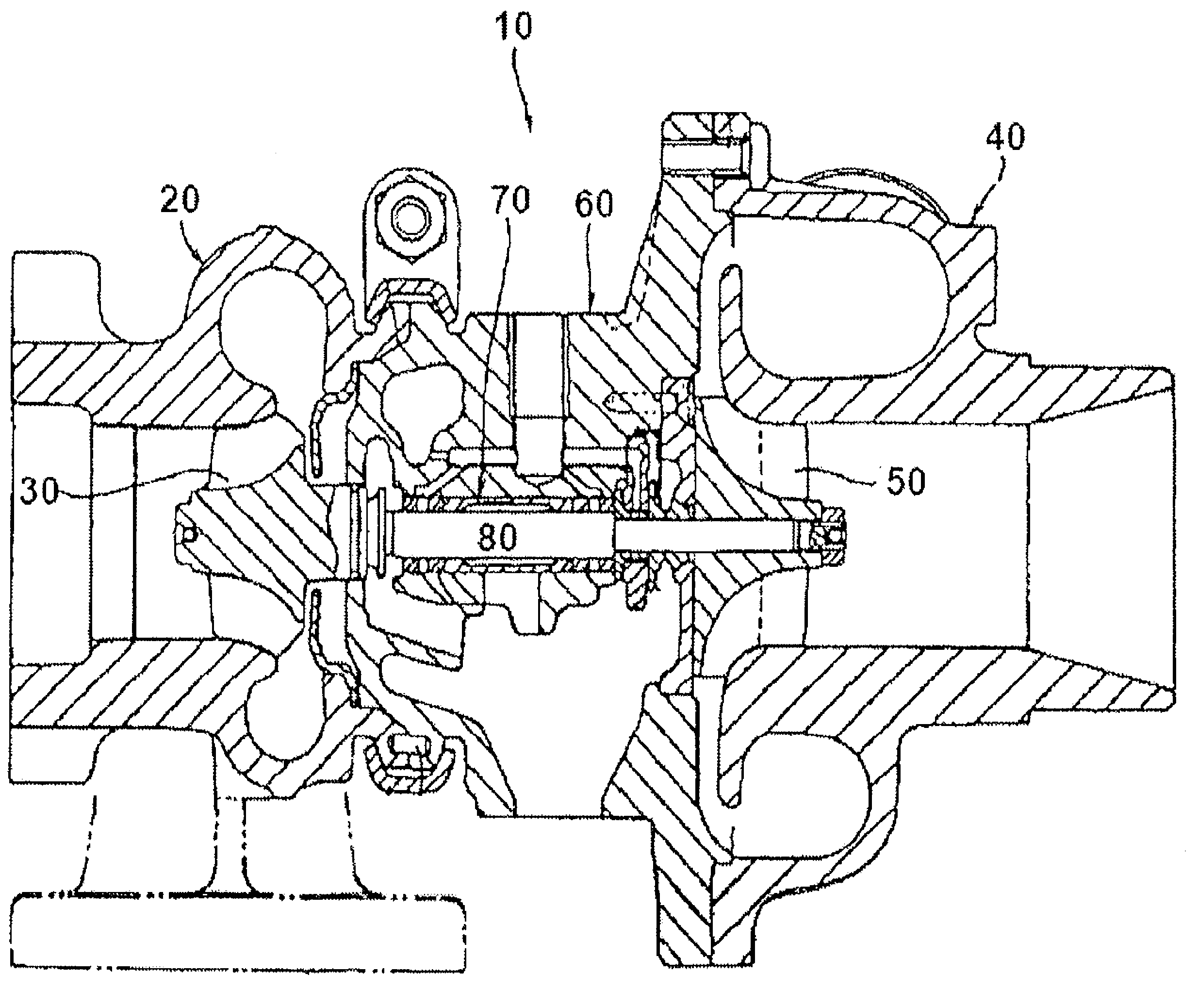
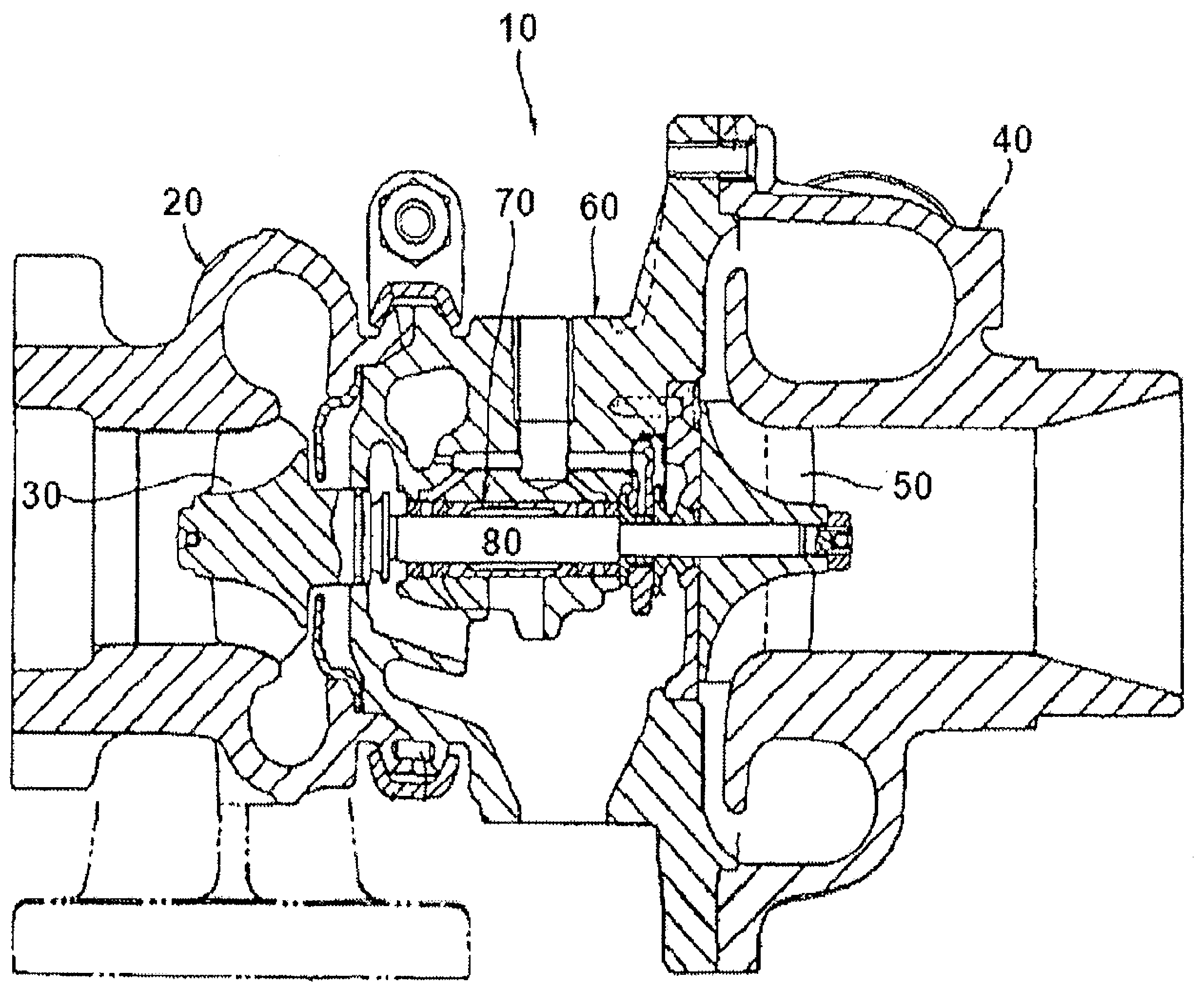
Because the turbocharger housing and, in particular, the turbine housing of a turbocharger comprises the greatest weight, it also comprises the greatest cost of the entire turbocharger.
Thus, the cost of the end product must be dramatically increased to account for the high cost of the nickel.

Method used


Image

  • Austenitic ductile cast iron
  • Austenitic ductile cast iron

Examples


example 1

Alloy Formulation

[0066]

TABLE 1Alloy FormulationInventive AlloyElement(D-3.5)D-5SC2.291.76Ni28.0134.01Cr2.522.09Si3.855.18Mo0.880.033Mn0.120.26Mg0.0660.057P0.0130.038S0.0050.003Cu0.030.03

example 2

Representative Tensile Testing, Conducted at High Strain Rate of 1% / s as per ASTM E8M 2004 (Published May 2004)

[0067]

TABLE 2Temperature (° C.)251005006007008009001000Yield Strength Re (Mpa)D-5S217.9188.2168.8161.7157.2164.2102.459.5D-3.5240.0214.2200.3193.8181.8182.6133.191.3Ultimate Tensile Strength Rm (Mpa)D-5S440.7383.6366.7334.8279.5177.1103.361.0D-3.5387.9357.9356.9302.7291.3206.1148.091.6Young Modulus E (Gpa)D-5S141.3128.290.076.967.785.351.167.1D-3.5127.7120.891.9101.899.766.573.764.3

example 3

Representative Fatigue Testing, Conducted as per ASTM E606 1992 (Published March 1993)

[0068]

TABLE 3Strain Controlled Low Cycle Fatigue Testing (High StrainRate Testing (1% / s) with R Ratio of −1) (Total strainamplitude is given above)Temperature (° C.)500600700D-5S0.51.50.41.50.41.55700260100701906570220D-3.50.51.50.41.50.41.5107051401560070823070

[0069]Note that the columns under each temperature in the table above indicate two different total strain rates. For example, the first cell 500 / 0.5 / D5S, with a value of 5,700 indicates that a low cycle fatigue test conducted at 500° C. with a total strain of 0.5% (which is for a maximum strain of 0.25% at an R ratio of −1, so a minimum strain of −0.25%) resulted in a failure after 5,700 cycles.


PUM

PropertyMeasurementUnit
ultimate tensile strengthaaaaaaaaaa
elongationaaaaaaaaaa
temperaturesaaaaaaaaaa

Abstract

The invention provides an austenitic ductile cast iron alloy composition including about 2.2% to about 2.4% by weight carbon; about 3.5% to about 4.0% by weight silicon; about 28% to about 29% by weight nickel; about 2.5% to about 3.0% by weight chromium; about 0.9% to about 1.1% by weight molybdenum; and greater than about 50% iron, wherein percentages are based on the overall weight of the composition. The invention further provides articles, such as turbocharger housings, prepared using the inventive alloys.

Description

FIELD OF THE INVENTION[0001]The invention relates to alloy compositions useful in the preparation of articles for use in applications where high heat resistance is desired. The alloy compositions are particularly iron-based alloys.BACKGROUND[0002]Austenitic ductile irons are well known and have been used for many years in a wide range of applications requiring materials with specific chemical, mechanical, and physical properties. Ductile cast irons are cast irons containing graphite in the form of substantially spheroidal particles produced by suitable molten metal treatment. Spheroidal graphite has a polycrystalline radial structure. There are a number of different austenitic ductile iron types defined in the literature. The austenitic ductile iron types are defined based in part on their chemical makeup, comprising various amounts of iron, nickel, silicon, and carbon and, in some iron types, additional elements such as manganese, phosphorus, chromium, and molybdenum. These latter ...

Claims


Application Information

Patent Timeline
Patent Type & Authority Patents(United States)
IPC IPC(8): C22C37/04C22C37/08C22C37/10
CPCC21D5/00C22C37/04C22C37/08F01D25/24C21D2211/001F05D2220/40F05D2300/111F05D2300/502F05D2300/518C22C37/10
Inventor CLAUDE, ANTOINEWILSON, MARCBENCHIHEUB, RAYADSCHMITT, LYDIE TENETROUILLON, ANGELIQUE
Owner GARRETT TRANSPORATION I INC
Why Eureka
Try Eureka