Electrolytic igniter for rocket engines using liquid propellants

a technology of electric ignitor and rocket engine, which is applied in the field of electric ignitor for rocket engine using liquid propellant, can solve the problems of high toxicity, additional complication, and specific impulse that is limited in practice to 330 seconds, and achieves reliable ignition, high degree of flexibility, and time saving

Inactive Publication Date: 2013-02-19
ARIANEGRP SAS
View PDF12 Cites 5 Cited by
  • Summary
  • Abstract
  • Description
  • Claims
  • Application Information

AI Technical Summary

Benefits of technology

[0032]The invention also seeks to provide a high degree of flexibility in the use of an ignitor on a main stage of a launcher, in particular in the event of an aborted launch, such that no intervention on the ignitor is needed before attempting the following launch, thereby saving time that may amount to several days.
[0033]The invention also seeks to enable the ignitor device to be such that the thruster does not need to be subjected to any modification between reception testing and launch.
[0034]The invention also seeks to propose an ignitor of simplified construction and that, in particular, does not raise safety problems, does not require the use of a laser beam, and provides reliable ignition for a combustion chamber regardless of its size, with a very high level of instantaneous power being delivered.
[0048]The invention reproduces substantially all of the advantages of laser ignition and in particular the fact of it being possible for the ignition zone to be situated at a distance from solid walls, without suffering the above-mentioned drawbacks associated with the fragilities and the complexities of using a device for producing and applying a laser beam.

Problems solved by technology

Self-ignition makes use of self-igniting propellants such as mono-methyl hydrazine (MMH) and nitrogen peroxide (N2O4), which are well known, but which present high levels of toxicity and provide a specific impulse that is limited in practice to 330 seconds.
Nevertheless, self-ignition leads to an additional complication.
Certain liquids that self-ignite with oxygen, such as organometallic compounds, are spontaneously combustible in air, toxic, and cause burns by contact.
They therefore present safety problems.
In both circumstances, the high voltage used (10 kilovolts (kV) to 20 kV) can give rise to difficulties.
Hydrazine is a mono-propellant that decomposes catalytically and that also presents a high level of toxicity.
This solution appears not to be used in operational manner for igniting cryogenic rocket engines.
The same problem arises with thrusters of smaller size, which are ignited directly by a spark plug.
Nevertheless, that method is not easily transposed to an operational rocket engine, given the problems associated with on-board laser technology, with the ability of an optical fiber to withstand vibration, with the behavior of the window through which the laser beam enters the combustion chamber, and with the behavior of the focusing optics.

Method used


Image

  • Electrolytic igniter for rocket engines using liquid propellants
  • Electrolytic igniter for rocket engines using liquid propellants
  • Electrolytic igniter for rocket engines using liquid propellants

Examples


Embodiment Construction

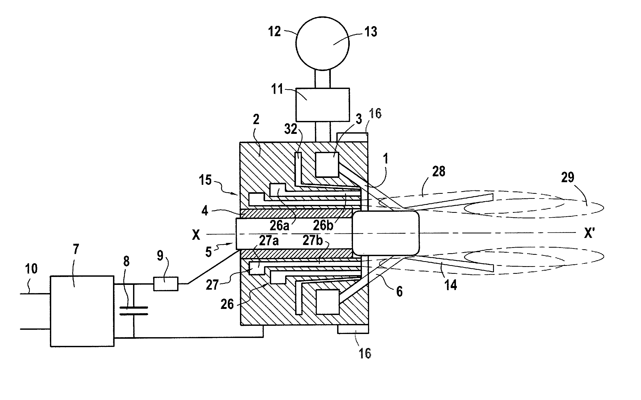
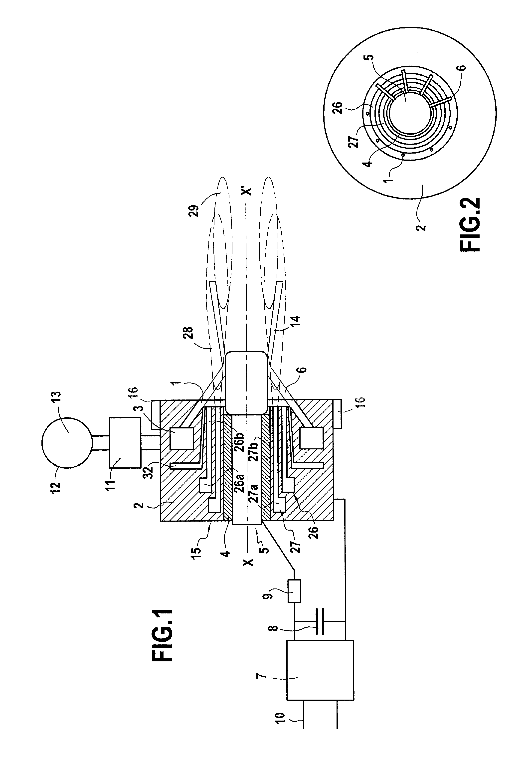
[0075]With reference to FIG. 1, there can be seen a first example of an electrolytic ignitor of the invention designed to be incorporated in a torch associated with a main injector that is to be mounted in a combustion chamber of a liquid-propellant rocket engine.

[0076]The electrolytic ignitor comprises an injector that, in the example described, presents a potential close to electrical ground and constitutes a cathode.

[0077]In conventional manner, the injector 2 comprises a fuel injector device 26 and an oxidizer injector device 27.

[0078]As can be seen in FIG. 2, the fuel injector device 26 and the oxidizer injector device 27 comprise respective distribution channels 26a, 27a and delivery orifices 26b, 27b distributed in a ring around the central axis XX′ of the injector.

[0079]The injector 2 also includes an electrolytic injector device with an electrolyte distribution channel 3 associated with a plurality of injection holes 1 enabling free jets to be projected towards a central el...


PUM


Abstract

The electrolytic ignitor comprises an injector constituting a first electrode and including a fuel injector device, an oxidizer injector device, and an electrolyte injector device. A second electrode electrically insulated from the injector extends downstream beyond the injector. An electrolyte distribution channel for delivering electrolyte in the form of free jets through the electrolyte injector device comprises at least one injection hole in the vicinity of the fuel injector device and the oxidizer injector device. An electrical power supply circuit is adapted to raise the second electrode to a potential in the range 50 V to 1000 V relative to the potential of the first electrode. The electrolyte injected through the injection hole is capable of causing ignition of a gaseous mixture in a combustion chamber of an ignitor torch suitable for incorporating in a main injector of a rocket engine.

Description

FIELD OF THE INVENTION[0001]The present invention relates to an electrolytic ignitor for a rocket engine using liquid propellants, in particular cryogenic propellants.[0002]The invention thus relates more particularly to a torch ignitor for a cryogenic engine and to an ignition torch suitable for incorporating in a main injector of a liquid-propellant rocket engine.PRIOR ART[0003]Rocket engines fed with liquid propellants are generally ignited by self-ignition or by pyrotechnic ignition, or by electrical ignition using a torch.[0004]Self-ignition makes use of self-igniting propellants such as mono-methyl hydrazine (MMH) and nitrogen peroxide (N2O4), which are well known, but which present high levels of toxicity and provide a specific impulse that is limited in practice to 330 seconds.[0005]Some rocket engines operating on liquid oxygen and hydrocarbon are ignited by injecting a self-igniting liquid together with liquid oxygen, e.g. using an organometallic compound (as is done in th...

Claims


Application Information

Patent Timeline
Patent Type & Authority Patents(United States)
IPC IPC(8): F02C7/264
CPCF02K9/52F02K9/95H05H1/48H05H2001/3484H05H1/3484H05H1/34
Inventor VALENTIAN, DOMINIQUE
Owner ARIANEGRP SAS
Why Eureka
Try Eureka