Magnetic field strength threshold alarm

a technology of magnetic field and threshold alarm, which is applied in the direction of magnets, instruments, applications, etc., can solve the problems of ferromagnetic objects being attracted to the strong magnetic field, the need for the magnet to be kept, and the inability to quickly turn off the superconducting mri magn

Active Publication Date: 2013-02-19
KOPP DEV
View PDF23 Cites 10 Cited by
  • Summary
  • Abstract
  • Description
  • Claims
  • Application Information

AI Technical Summary

Problems solved by technology

Most new magnets for MRI are superconducting and as a result very expensive to start up, causing the requirement for the magnet to be kept always on.
In an emergency, these superconducting MRI magnets cannot be turned off quickly.
The strong magnetic field associated with the area near to the MRI presents a danger of ferromagnetic objects being attracted to the strong magnetic field.
There are numerous recorded incidents of objects becoming flying projectiles resulting in injury to the nearby personnel or the patient.
Costly damage may be caused to the MRI machine itself from the impact of the projectile.
As a result, ferromagnetic detectors do not prove useful in this situation other than to alert personnel that a potential risk may be present.
In addition to the potential projectile risk posed by medical equipment brought into the magnetic field of the MRI, many medical devices do not function correctly or are damaged when operated in high magnetic fields.
The equipment may, therefore, be easily moved or accidently bumped into an area where the magnetic field is dangerously high.
As a result, the personnel may not be aware of the present danger.
Any piece of electrical or electronic equipment operating inside this screen room can be a potential source of interference.
Electromagnetic interference can cause a degradation of the diagnostic quality of the image produced by the MRI process.
Even after this validation process, there is still a significant risk that the MRI image quality may be compromised.
As such, a power cord supplying electricity to the equipment is inconvenient as well as being a potential risk of electromagnetic interference.
Further, since the disclosed invention must be powered at all times while the device is in the screen room, there is a significant risk of the device causing electromagnetic interference.
This approach has potential of lowering the power consumption of the device under certain circumstances.
Further, the risk of electromagnetic interference with the MRI machine is still present since the device is powered while it is in the MRI room.
The risk of electromagnetic interference may actually be increased by the presence of RFID circuitry.

Method used


Image

  • Magnetic field strength threshold alarm
  • Magnetic field strength threshold alarm
  • Magnetic field strength threshold alarm

Examples


Embodiment Construction

[0028]Example embodiments that incorporate one or more aspects of the invention are described and illustrated in the drawings. These illustrated examples are not intended to be a limitation on the invention. For example, one or more aspects of the invention can be utilized in other embodiments and even other types of devices. Moreover, certain terminology is used herein for convenience only and is not to be taken as a limitation on the invention.

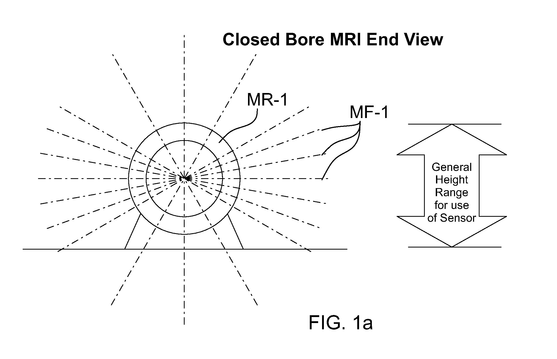
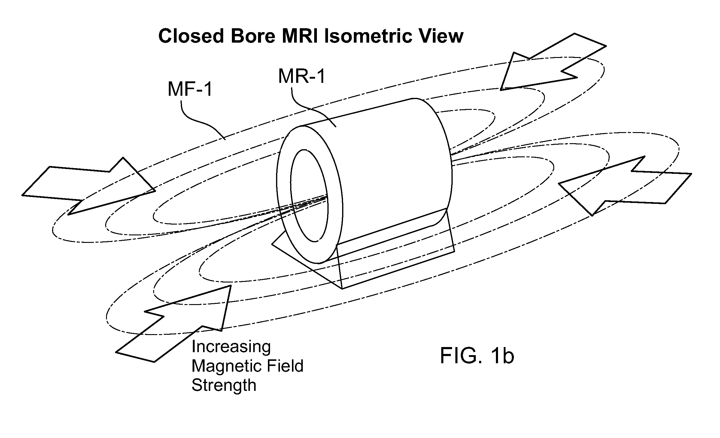
[0029]A schematic example of a closed bore magnetic resonance imager (MRI) is shown within FIGS. 1a and 1b. It can be seen that that the magnetic field MF-1 surrounding the MRI magnet MR-1 is substantially horizontal. In accordance with one aspect of the present invention, in order to efficiently sense such a magnetic field a sensor could rely on a relationship that the torque on a magnet is the vector cross product of the magnetic dipole moment of the magnet and the external magnetic field.

[0030]Turning to FIG. 3 an example of a magnetic fi...


PUM

PropertyMeasurementUnit
magnetic fieldaaaaaaaaaa
strengthaaaaaaaaaa
electricalaaaaaaaaaa

Abstract

A magnetic field strength threshold alarm that includes sensing means responsive to a magnetic field and actuating in response to field strength above a predetermined threshold, the sensing means being configured to be operational and able to actuate without consumption of energy; and alarm means for outputting an alarm responsive to the sensing means actuation, the alarm means being configured not to consume energy prior to actuation of the sensing means and only consuming energy subsequent to actuation of the sensing means. So, energy is not consumed by the alarm means prior to actuation. The alarm may be considered to include energy storage means for providing electrical energy, wherein the sensing means, the alarm means and energy storage means being operatively connected such that the electrical energy from the energy storage means is provided only when the sensing means is actuated.

Description

FIELD OF THE INVENTION[0001]The present invention is in the field of devices or apparatus for detecting magnetic strength in the vicinity of an operating magnetic resonance imager (MRI) and responding when a preset magnetic field strength is exceeded.BACKGROUND OF THE INVENTION[0002]The MRI has become an invaluable tool for imaging and exploring the internal anatomy without surgery. MRI has the ability to distinguish healthy from diseased tissue, fat and muscle and adjacent structures within the body which other modalities cannot differentiate. MRI uses safe radio waves and a strong magnetic field to generate the information, which is processed by a computer, to create an image. There are now about 10,000 MRI machines currently in use in the United States.[0003]Because of the desire for higher quality and higher resolution, the static magnetic field strength has increased steadily over the last 25 years, from a fraction of a Tesla to the current situation where 3 Tesla magnets are c...

Claims


Application Information

Patent Timeline
Patent Type & Authority Patents(United States)
IPC IPC(8): G01R33/02G08B21/02H01F7/02
CPCA61B5/055B82Y25/00G01R33/0385G01R33/288
Inventor KOPP, KEITHDEMENT, HAROLD DUANE
Owner KOPP DEV
Why Eureka
Try Eureka