Wind energy installation comprising a wind speed measuring system

a wind energy installation and measuring system technology, applied in the direction of liquid/fluent solid measurement, machines/engines, instruments, etc., can solve the problems of not being able to measure the speed of a single particle, not being able to adapt to the measurement of wind speed, and affecting the measurement effect of optical fiber, etc., to achieve the effect of not excessively consuming energy

Inactive Publication Date: 2013-02-26
SIEMENS AG
View PDF7 Cites 6 Cited by
  • Summary
  • Abstract
  • Description
  • Claims
  • Application Information

AI Technical Summary

Benefits of technology

[0009]It is an object of the invention to create a wind energy installation with a wind speed measurement system which does not show the disadvantages of the known techniques and which might be used on a regular basis without excessive energy consumption.
[0015]Furthermore it might be of advantage that the installation further comprises a control and analysing unit, which analyses the reflected light from the at least one sensor and calculates a shift of the frequency as a difference of the frequency of the emitted light and the frequency of the reflected light as result of vibrations of the optical fiber and therefore calculates the wind speed of the wind passing the optical fiber. Furthermore the control and analysing unit may control the pitch of the blades.
[0017]Furthermore it is of advantage that a plurality of Bragg grid grating sensors are located at different positions within the optical fiber. Therefore the distance between the different Bragg grid grating sensors allows a local resolution of the wind speed measurement to measure the wind speed at different spots of the installation at almost the same time or in a serial measuring application.

Problems solved by technology

Accordingly it is not easily achievable to measure the speed of a single particle to determine the speed of the air at a predetermined location or spot at the wind energy installation or in the vicinity of the rotor blades.
Furthermore the measurement equipment and the method are both rather complicated and not adapted to measure the wind speed during the whole operation time of the system.
The above mentioned technology has the striking drawback that the optical fiber has to be heated all the time at a very constant temperature in order to measure the wind speed with an expected degree of accuracy.
The heating of the fiber consumes electrical energy and is this energy consumption is therefore strongly inefficient and not acceptable for a standard use during extended time periods.
In case of a use only from time to time including periods of time without wind speed measurement the wind energy installation reveals a great disadvantage with regard to safety of the installation itself.

Method used


Image

  • Wind energy installation comprising a wind speed measuring system
  • Wind energy installation comprising a wind speed measuring system
  • Wind energy installation comprising a wind speed measuring system

Examples


Embodiment Construction

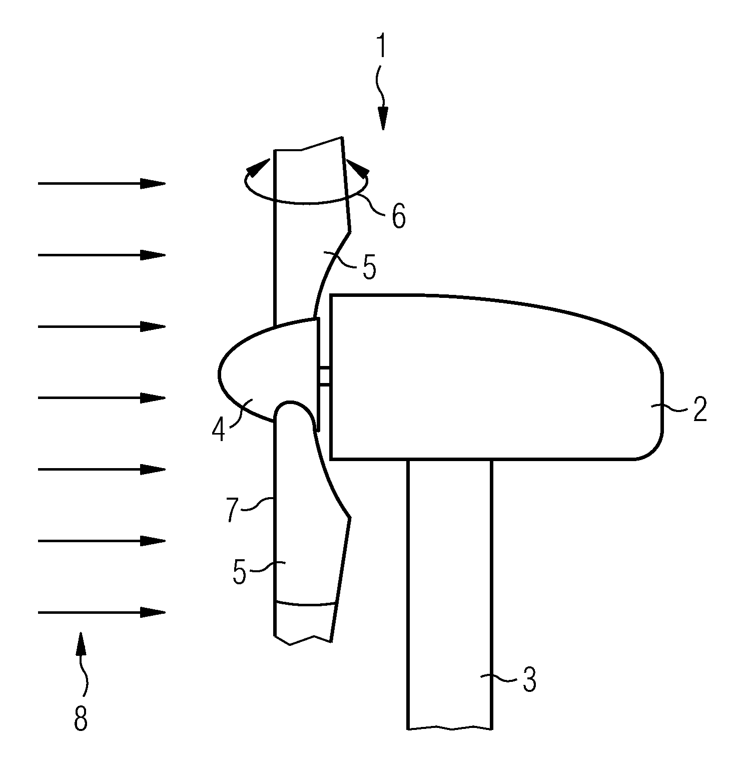
[0025]FIG. 1 shows schematically a wind energy installation 1 comprising a nacelle 2 which is mounted on top of a pylon 3 and which comprises a rotor 4 comprising at least one rotor blade 5. The embodiment of FIG. 1 shows two rotor blades 5. In order to tune the rotor blades 5 e.g. due to wind speed and wind direction the blades 5 are pivot-mounted within the rotor 4 as indicated by arrow 6.

[0026]In order to measure the wind speed of the wind 8 blowing at the vicinity of the installation 1 the installation 1 comprises at least one optical fiber 7 which allows to measure the wind speed by way of measurement of vibrations of the optical fiber 7 originated by vortex shedding.

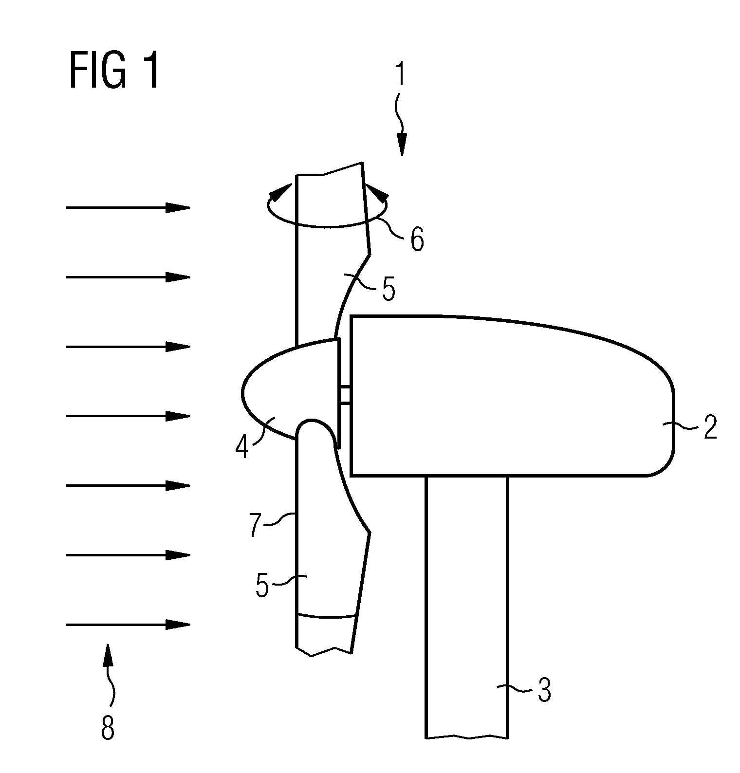
[0027]FIG. 2 shows an example of a cross-section of a rotor blade 5 which contains an optical fiber 7 at the leading edge 9 of the blade 5. The fiber 7 is located at the leading edge and is fixed at a certain distance from the leading edge such that the fiber 7 is able to vibrate due to vortex shedding.

[0028]FIG. 3...


PUM


Abstract

A wind energy installation is disclosed. The wind energy installation includes a rotor with at least one rotor blade. The wind energy installation includes at least one wind speed measuring system. The at least one wind speed measuring system optically measures the vibrations of an optical fiber due to vortex shedding.

Description

CROSS REFERENCE TO RELATED APPLICATIONS[0001]This application is the US National Stage of International Application No. PCT / EP2009 / 058156, filed Jun. 30, 2009 and claims the benefit thereof. The International Application claims the benefits of European application No. 08012067.8 filed Jul. 3, 2008. All of the applications are incorporated by reference herein in their entirety.FIELD OF THE INVENTION[0002]The invention relates to a wind energy installation comprising a wind speed measuring system.BACKGROUND OF THE INVENTION[0003]The invention relates to a wind energy installation or windmill comprising a wind turbine comprising a rotor and at least one or a plurality of rotor blades. Such wind energy installations are typically installed in regions with high potential of wind energy to increase the amount of electrical energy generated using such wind energy installation. Usually the at least one rotor blade or the plurality of rotor blades are very large and might be tuned e.g. in an...

Claims


Application Information

Patent Timeline
Patent Type & Authority Patents(United States)
IPC IPC(8): G01F1/20
CPCF03D11/00G01P5/01F05B2260/80Y02E10/722F05B2270/32F03D17/00
Inventor BOSSELMANN, THOMAS
Owner SIEMENS AG
Why Eureka
Try Eureka