Fluid delivery system and method

a technology of fluid delivery system and liquid transfer device, which is applied in the field of fluid delivery system and method, can solve the problems of short shelf life, reduced usefulness of the system in the field, and increased cost and sophistication of fluid delivery to the platform

Active Publication Date: 2013-03-05
PRESIDENT & FELLOWS OF HARVARD COLLEGE
View PDF130 Cites 35 Cited by
  • Summary
  • Abstract
  • Description
  • Claims
  • Application Information

AI Technical Summary

Problems solved by technology

While various microfluidic devices and methods, such as microfluidic assays, can provide inexpensive, sensitive and accurate analytical platforms, fluid delivery to the platform can add a level of cost and sophistication that may require testing to be performed in a laboratory rather than in the field, where it may be most useful.
A portable microfluidic system can be transported to almost any location, but when reagents must be freshly prepared, the usefulness of the system in the field can be diminished.
This may be true in particular for biological and biochemical based systems that may rely on reagents that, for example, are unstable, have short shelf lives or must be stored under special conditions, such as refrigeration.

Method used


Image

  • Fluid delivery system and method
  • Fluid delivery system and method
  • Fluid delivery system and method

Examples


examples

[0132]An experiment was designed and run to evaluate the use of a heterogeneous immunoassay in combination with a cartridge containing a series of fluid plugs. All required reagents, except for the sample, were contained in the cartridge.

[0133]Photomasks for photolithography were obtained from PageWorks (Cambridge, Mass.). Negative photoresist SU8 was obtained from Microchem (Newton, Mass.). Poly(dimethylsiloxane) Sylgard184 (PDMS) was obtained from Dow Corning (Midland, Mich.). Polystyrene substrates were purchased from NUNC (Rochester, N.Y.). Rabbit, anti-rabbit and mouse immunoglobulin G (IgG) were purchased from Sigma (St-Louis, Mo.), and Alexa-488 donkey anti-sheep IgG was obtained from Molecular Probes (Eugene, Oreg.). A hand-operated vacuum pump and polyethylene tubing (Intramedic PE-60, 0.76 mm internal diameter and 1.22 mm external diameter) were purchased from VWR Scientific Products (Pittsburgh, Pa.). All other chemicals were of analytical grade and are available from che...

example 2

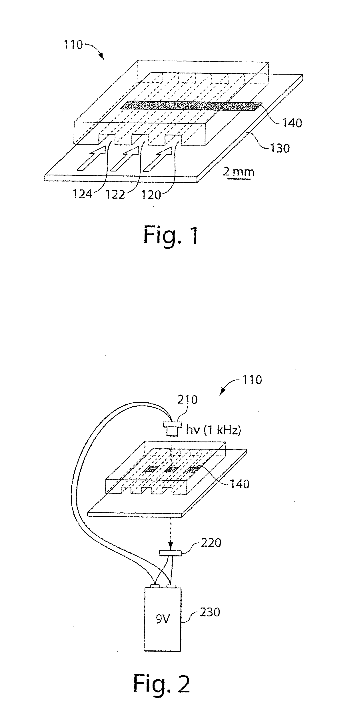
[0159]A schematic representation of one embodiment and an optical detection device is provided in FIG. 9. (A) Red light from the laser diode passes through the silver-coated microwell containing the sample to the optical IC. A pinhole was used to block stray light that did not pass through the sample. The laser diode and the optical IC were driven by the same circuit, which also had an integrated liquid crystal display that showed the measured transmittance value.

example 3

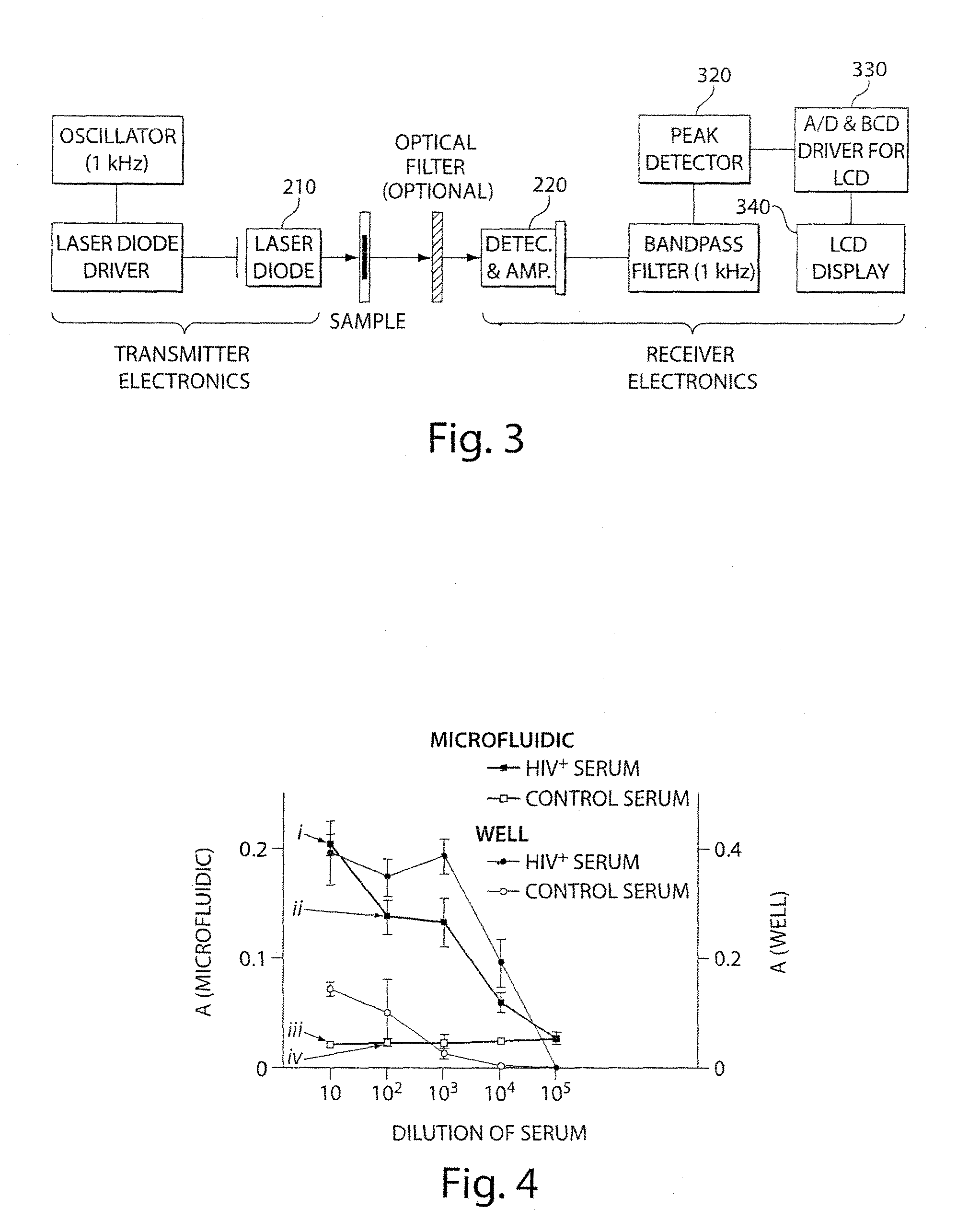
[0160]FIG. 10 provides a comparison of readings of an immunoassay using an optical IC and a UV-visible plate reader. An immunoassay using silver reduction was performed on a 96-well plate that detected rabbit IgG. Optical micrographs of the silver films on microwells are shown for each sample. The apparent absorbance of each microwell was measured by an optical IC, and compared to its reading by a UV-visible plate reader; both measurements were made at 654 nm. The best-fit line by linear regression has a correlation coefficient of 0.989, slope of 1.12, and y-intercept of 0.16.


PUM

PropertyMeasurementUnit
inner diameteraaaaaaaaaa
lengthaaaaaaaaaa

Abstract

A method and apparatus for delivering one or more fluids. Fluids may be delivered sequentially from a common vessel to a chemical, biological or biochemical process.

Description

RELATED APPLICATIONS[0001]This application is a continuation of U.S. application Ser. No. 10 / 587,156, filed May 16, 2007, which is a U.S. National Application of International Application No. PCT / US2005 / 003514, filed Jan. 26, 2005, which claims benefit under 35 U.S.C. §119(e) of U.S. Provisional Application Ser. No. 60 / 539,358, filed Jan. 26, 2004, U.S. Provisional Application Ser. No. 60 / 539,416, filed Jan. 26, 2004 and U.S. Provisional Application Ser. No. 60 / 565,866, filed Apr. 26, 2004, all of which are which are incorporated herein by reference.GOVERNMENT FUNDING[0002]This invention was made with government support under GM051559 awarded by National Institutes of Health and under ECS-0004030 awarded by National Science Foundation. The government has certain rights in the invention.BACKGROUND OF INVENTION[0003]1. Field of Invention[0004]This invention relates to a method and apparatus for the delivery and / or storage of one or more fluids and, in particular, to a method and appar...

Claims


Application Information

Patent Timeline
Patent Type & Authority Patents(United States)
IPC IPC(8): C12M1/34B01J4/02B01L3/00
CPCB01L3/0293G01N33/543G01N35/1002B01L3/5027B01L2200/0673B01L2200/16G01N35/08G01N35/1065B82Y30/00Y10T137/0318B01L2300/0816B01L3/502784G01N33/5304
Inventor LINDER, VINCENTSIA, SAMUEL K.WHITESIDES, GEORGE M.
Owner PRESIDENT & FELLOWS OF HARVARD COLLEGE
Why Eureka
Try Eureka