Rolling diaphragm pressure sensor

a diaphragm and pressure sensor technology, applied in the field of pressure measurement, can solve the problems of wall thickness variation, pressure sensitivity variation, and pressure sensitivity variation, and achieve the effect of clear and accurate pressure reading

Inactive Publication Date: 2013-03-19
SLOCUM SR ALEXANDER HENRY +1
View PDF19 Cites 18 Cited by
  • Summary
  • Abstract
  • Description
  • Claims
  • Application Information

AI Technical Summary

Benefits of technology

[0019]Another object of the invention is to taper at least one of the outer or inner tubes or the wall thickness so the sensitivity and linearity of the device to pressure can be controlled.
[0022]A still further object of the invention is to provide a sensor where the sensor when pressurized inside its enshrouding protective structure and held in any orientation will not suffer from any friction forces that substantially affect its ability to unroll in response to any applied pressure to be sensed; where in fact increased pressure pushes the outer tube up against the enshrouding structure to support it and give a clear and accurate reading of pressure.
[0023]A still further object of the invention is that it can be incorporated into the plunger of a syringe were sealing forces between the plunger and outer barrel can provide an excellent seal, and also create static friction forces to maintain the plunger's axial position when finger forces are removed from the plunger, thus allowing a user to periodically visually check the pressure and if needed, adjust the position of the plunger to maintain position while indicating a true and accurate pressure reading proportional to the sensor's extension.

Problems solved by technology

Conventional bellows can be used to measure pressure by visually monitoring extension of the bellows; however, bellows are difficult to manufacture with thin enough walls for measuring very low pressures, and variations in wall thickness during manufacturing can lead to significant variations in pressure sensitivity.
One of the causes of wall thickness variation is the difficulty with which the convolutions are made; most bellows are made using blow molding which does not lead to accurate wall thickness, particularly in the corners, and error in thickness in the corners leads to variation in effective diameter.
This makes measurement of very small pressures, on the order of millibar to centibars, very difficult.
If the bellows can be injection molded, greater thickness control can be obtained, but then the issue is how to remove the bellows from the mold without breaking the bellows?
Once again, it becomes difficult to make thin bellows for accurate low pressure measurement.
Hence they would be poor for measuring pressure.
No structure is perfect, and hence pressure will cause some radial motion and thus contact between the end of the bellows and the outer wall.
For larger pressures the bellows will tip and make contact with the wall of the enshrouding structure, and the resultant drag force will create an error in pressure measurement.
The patent shows an increase in the bellows end diameter or a connection between the bellow's end and a piston which are both attempts to keep the bellows centered, but no matter what, if there is mechanical contact, and upon application of pressure there will be, there will be a parasitic friction force that causes error in pressure measurement.
Furthermore, in this compression design, the wall thickness of the bellows cannot be too thin or in compression the bellows will buckle; hence it is inherently limited in how small a pressure it can sense while providing reasonable amount of axial compression so as to make it easy to discern visually by the user.
The only problem is that the device simply will not work because the balloon will not expand in a near fashion with pressure because the physical contact of the balloon with the chamber walls will constrain it and prevent it from extending axially.
This addresses the issue of controlling endotracheal cuff pressure in a very different way, and does not enable the doctor to change the pressure in accordance with what the patient or procedure may require.
U.S. Pat. No. 5,103,670 is from the family of pressure gage instruments where the function of the bellows is to contain the air pressure and transfer the forces to an indicator (rotary) mechanism, but as such the mechanism has considerable sliding friction and hence there will be substantial errors in measurement for low pressures.
U.S. Pat. No. 4,114,458 functions in a similar manner and has similar fatal drawbacks with regard to precision pressure measurement.
U.S. Pat. No. 4,966,035 replaces the bellows with a spring, piston and seal and thus has even greater parasitic errors.
Hence any pressure forces generated will first have to overcome the static friction sealing forces and a large error in measurement will occur.
Hence it might only present a reasonable visual displacement for a substantial fraction of one atmosphere of pressure.
Furthermore, it will not provide the same reading in Denver as in Los Angeles or anyplace where the barometric pressure is different than from where it was manufactured.
Since the bellows elasticity is in series with the plunger and the fluid line leading from it, there is no way to ascertain what portion of the force on the plunger is due to the pressure in the line and that due to the elasticity of the bellows.
In addition, lateral motion of the plunger would create contact with the enshrouding cylinder walls creating a parasitic force further reducing accuracy.
Once again, there can be no true accurate indication of pressure.
Furthermore, there is a fundamental problem associated with using an axially compliant cantilevered member to measure pressure: axial compliance equates to a low effective modulus of elasticity, which in turn means that gravity will cause any such structure to sag considerably under its own weight; although the modulus of elasticity of the rubber in a bellows may be several MPa, the convolutions make it effectively to be orders of magnitude lower so that any cantilever beam loaded under its own weight but having such a low modulus will droop substantially.
Once the drooping structure makes contact with the walls of a protective enclosure, a parasitic frictional force will be encountered which can cause significant pressure measurement errors if very fine pressure measurements attempted.
This large volume is undesirable if a fluid is the working media because the fluid must then be disposed of if the application is single use.
To one skilled in the art of pistons and seals, motion without friction can be accomplished by a rolling diaphragm seal; however, these seals are noted for having a very low constant force resistance, hardly suitable for pressure measurement.

Method used


Image

  • Rolling diaphragm pressure sensor
  • Rolling diaphragm pressure sensor
  • Rolling diaphragm pressure sensor

Examples


first embodiment

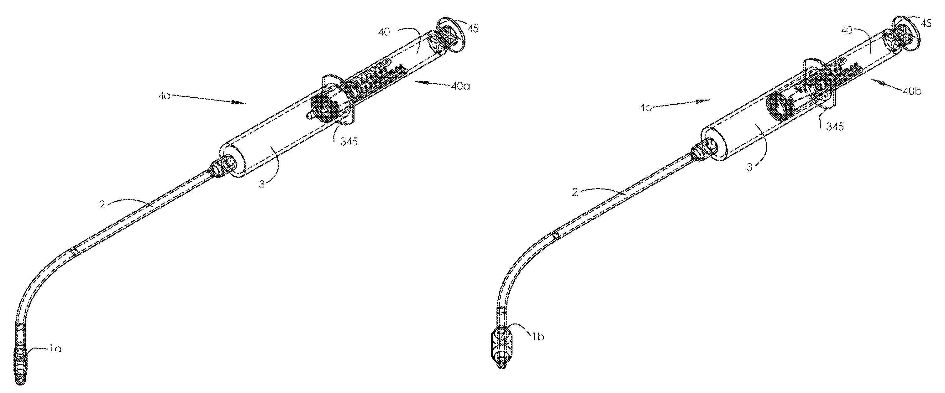
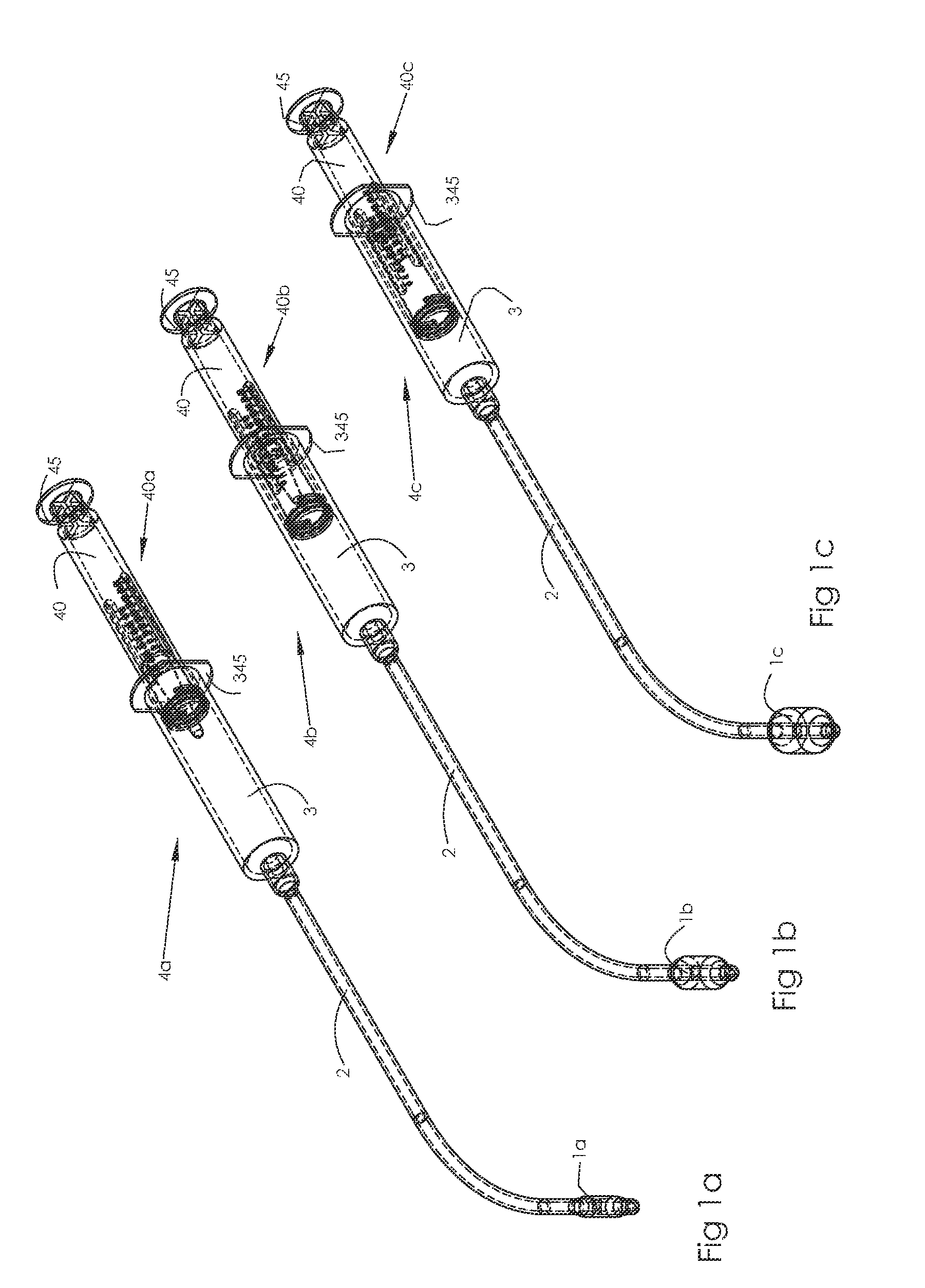
[0046]FIG. 4a shows an enshrouding structure 40 (also referred to as the plunger in a syringe application). It has slits 46 near its base that axially and rotationally constrain the sensor via the sensor's snap-in tabs 33c and 33c′. The sensor region 41 is comprised of a slot 42b, which is not needed if the plastic is very clear, and a scale 42a which can be molded integral or inked on or even be a label applied. Only one side is shown here, and for ergonomic reasons, multiple sets placed circumferentially around the structure 40 body can be used. The sensor region needs to be located and scaled in accordance with the sensor's sensitivity and size. Shown here, it is sized and labeled to indicate centimeters of water pressure. Note that the sensor region 41 (and its mirror image) is aligned with the slots 46 so the part can easily be molded with two halves and a simple core.

second embodiment

[0047]FIG. 4b shows an enshrouding structure 40′ (also referred to as the plunger in a syringe application). It also has slits 46 near its base that axially and rotationally constrain the sensor via the snap-in tabs 33c and 33c′. The sensor region 44 is comprised of cylindrical lens structures 43b that help magnify the end position of the sensor and makes it easier to read the position of the end of the sensor with respect to the scale 43a. The scale 43a which can be molded integral or inked on or even be a label applied. Only one side is shown here, and for ergonomic reasons, multiple sets placed circumferentially around the structure 40′ body can be used. The sensor region needs to be located and scaled in accordance with the sensor's sensitivity and size. Shown here, it is sized and labeled to indicate centimeters of water pressure. Note that the sensor region 44 (and its minor image) is aligned with the slots 46 so the part can easily be molded with two halves and a simple core....


PUM

PropertyMeasurementUnit
pressureaaaaaaaaaa
lengthaaaaaaaaaa
diameteraaaaaaaaaa

Abstract

A system for measuring and indicating pressure that uses as its pressure sensing element an outer resilient tube, an inner resilient tube, and a rolling diaphragm connecting the inner and outer tubes, and held inside a protective enshrouding structure where pressure applied to the annulus between the tubes causes the diaphragm to deform and roll to axial extend the outer tube by an amount proportional to the applied pressure. The structure has features that enable visual correlation of the partially rolled tube's unrolled state with the applied pressure. The system can be incorporated into a syringe to create a pressure measuring syringe for inflating endotracheal cuffs while providing a reading of the cuff pressure.

Description

[0001]The present invention relates to a device for very fine pressure measurements, either of very low pressures or of pressures with very high accuracy where the pressure causes a rolling diaphragm to change the observable length in an outer tube.STATEMENT REGARDING FEDERALLY FUNDED RESEARCH[0002]No federal funds were used in the development of this inventionFIELD OF THE INVENTION[0003]The present invention relates to the measurement of pressure where pressure causes a rolling diaphragm to change the observable length in an outer tube.BACKGROUND OF THE INVENTION[0004]There are a great many instruments for measuring pressure and fundamentally many rely on pressure causing mechanical deformation of a mechanical structure which then causes an indicator to move which allows the user to observe a value of pressure. In some fields, such as medical devices or where extreme purity of gases must be maintained, it is important to measure pressure with a single element that can be made from ...

Claims


Application Information

Patent Timeline
Patent Type & Authority Patents(United States)
IPC IPC(8): G01L7/08F16J15/50
CPCG01L7/086G01L7/082
Inventor SLOCUM, SR., ALEXANDER HENRYSLOCUM, JR., ALEXANDER HENRY
Owner SLOCUM SR ALEXANDER HENRY
Why Eureka
Try Eureka