Distributed head-mounted display system

a display system and head-mounted technology, applied in the direction of optics, instruments, optical light guides, etc., can solve the problems of direct display with poor image viewing quality, limiting factor of display quality within the device of the end-user, etc., to facilitate the exploitation of very compact light-guide optical elements, easy to incorporate, and large emb values

Active Publication Date: 2013-03-26
LUMUS LTD
View PDF9 Cites 42 Cited by
  • Summary
  • Abstract
  • Description
  • Claims
  • Application Information

AI Technical Summary

Benefits of technology

[0006]The present invention facilitates the exploitation of very compact light-guide optical element (LOE) for, amongst other applications, HMDs. The invention allows relatively wide FOVs together with relatively large EMB values. The resulting optical system offers a large, high-quality image, which also accommodates large movements of the eye. The optical system offered by the present invention is particularly advantageous because it is substantially more compact than state-of-the-art implementations and yet it can be readily incorporated, even into optical systems having specialized configurations.
[0007]A further application of the present invention is to provide a compact display with a wide FOV for mobile, handheld application such as cellular phones. In today's wireless market; sufficient bandwidth is available for full video transmission. The limiting factor remains the quality of the display within the device of the end-user. The mobility requirement restricts the physical size of the displays, and the result is a direct-display with poor image viewing quality. The present invention enables a physically very compact display with a very large virtual image. This is a key feature in mobile communications, solving one of the main limitations for its practical implementation. Thereby, the present invention enables the viewing of the digital content of a full format internet page within a small, handheld device, such as a cellular phone.
[0008]A broad object of the present invention is therefore to alleviate the drawbacks of prior art compact optical display devices and to provide other optical components and systems having improved performance, according to specific requirements.

Problems solved by technology

The limiting factor remains the quality of the display within the device of the end-user.
The mobility requirement restricts the physical size of the displays, and the result is a direct-display with poor image viewing quality.

Method used


Image

  • Distributed head-mounted display system
  • Distributed head-mounted display system
  • Distributed head-mounted display system

Examples


Embodiment Construction

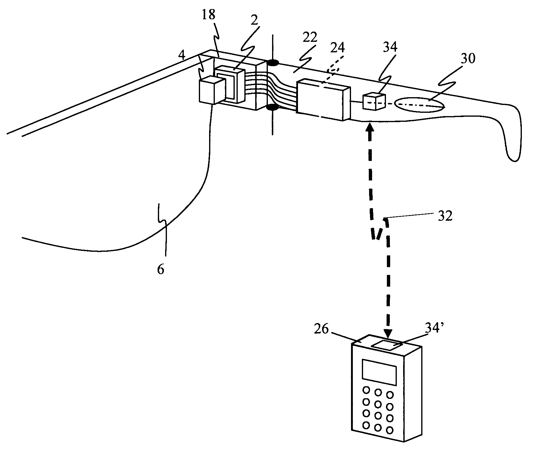
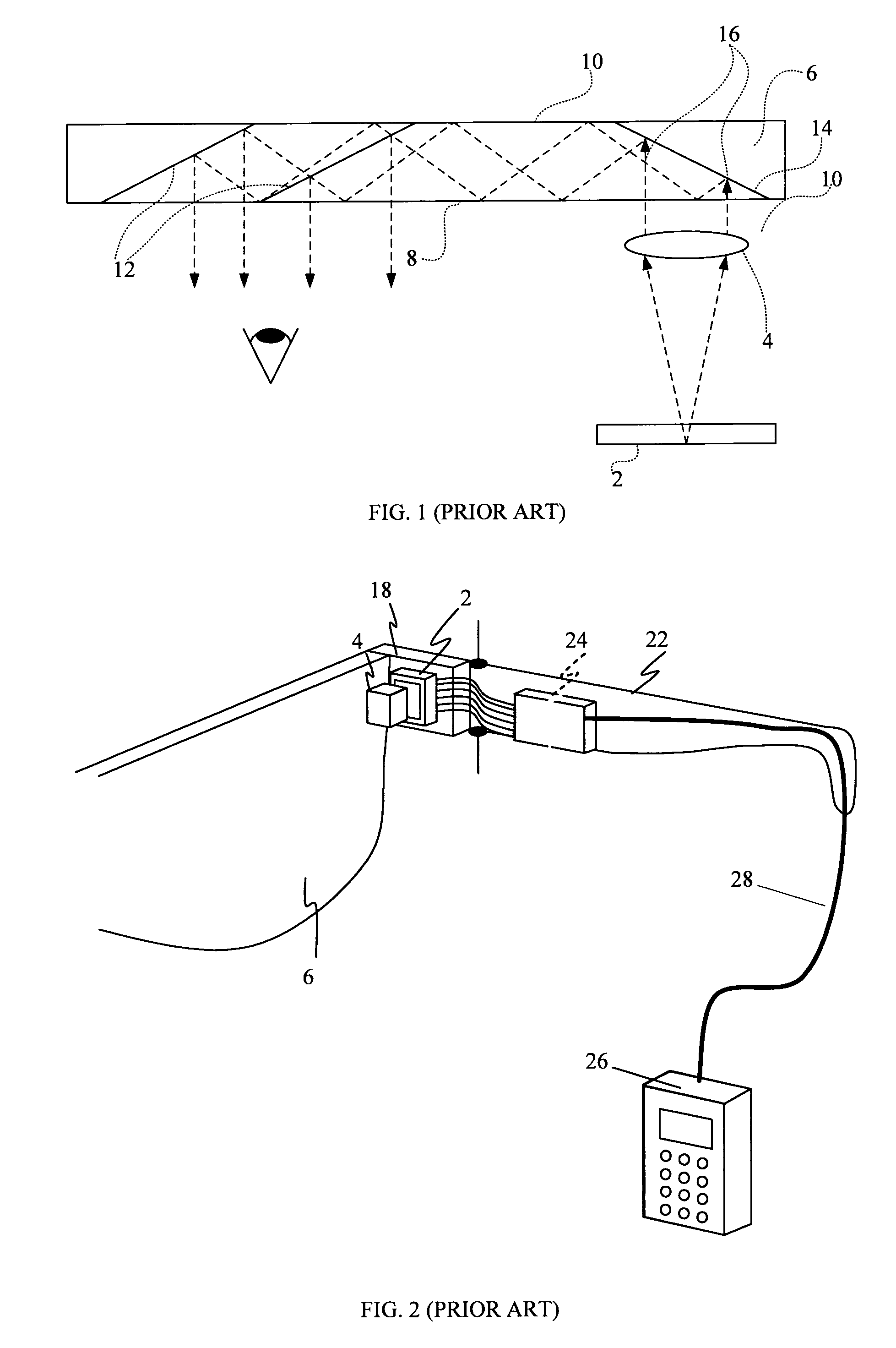
[0020]FIG. 1 illustrates a main optical module comprising a display source 2, a collimating device 4, e.g., a lens, and an LOE 6, to form an optical system. Such an LOE typically includes at least two major surfaces 8 and 10 and edges, at least one partially reflecting surface 12 and an optical element 14 for coupling light thereinto. The output waves 16 from the collimating device 4 enter the LOE 6 through its lower surface 8. The incoming waves (vis-à-vis the LOE) are reflected from the surface 14 and trapped in the LOE. The collimating device 4 can easily be integrated into a single mechanical module which may be assembled independently of the LOE, with fairly relaxed mechanical tolerances.

[0021]In general, all the potential configurations of the LOEs considered in the publications referred to above, offer several important advantages over alternative compact optics for display applications, which include:[0022]1) The input display source can be located very close to the substrat...


PUM


Abstract

There is provided an electro-optical system, including at least two spaced-apart units, a head-mounted display (HMD) unit, having a video signal source, a display source for displaying video signals from the display source, an optical module for projecting video signals from the display source into a user's eye, a driving electronic module, a power supply, and a portable control unit. The two spaced-apart units communicate by a narrowband wireless channel.

Description

FIELD OF THE INVENTION[0001]The present invention relates to distributed head-mounted display (HMD) systems, and in particular, to mobile systems that include two separate units: a head-mounted unit and a portable handheld control unit which communicate by a narrowband wireless channel.[0002]The invention can be implemented to advantage in a large number of imaging applications, such as portable DVDs, cellular phone, mobile TV receiver, video games, portable media players or any other mobile display devices.BACKGROUND OF THE INVENTION[0003]One important application for compact optical elements is in HMDs wherein an optical module serves both as an imaging lens and a combiner, in that a two-dimensional image source is imaged to infinity and reflected into the eye of an observer. The display source can be directly obtained from either a spatial light modulator (SLM) such as a cathode ray tube (CRT), a liquid crystal display (LCD), an organic light emitting diode array (OLED), a scanni...

Claims


Application Information

Patent Timeline
Patent Type & Authority Patents(United States)
IPC IPC(8): G09G5/00
CPCG02B27/017G02B27/0172G02B6/00
Inventor LAPIDOT, ZVIAMITAI, YAAKOVFRIEDMAN, SHMUEL
Owner LUMUS LTD
Why Eureka
Try Eureka