
Binary half-tone photolithographic optical apodization mask

Active Publication Date: 2013-04-02
LOCKHEED MARTIN CORP
View PDF6 Cites 16 Cited by
  • Summary
  • Abstract
  • Description
  • Claims
  • Application Information

AI Technical Summary

Benefits of technology

The patent describes a new method for creating an apodization mask that can produce uniform lighting and remove diffraction effects. The mask is made up of a randomized array of dots that are positioned to cancel out any diffraction patterns. The dots are arranged in a way that ensures no optical path length differences over the full area of the mask. This results in a smooth, uniform apodization that can be controlled to a high degree of accuracy. Overall, this method provides a more efficient and effective means of creating apodization masks for various applications.

Problems solved by technology

The required radial variation in optical density also results in a varying optical path length difference, which can amount to hundreds of nanometers.
With interferometers operating in the picometer range, this variation becomes unacceptable.
Conventional apodization masks present at least a number of problems for use with advanced interferometers.
Such uniquely shaped mask patterns, however, cannot be fabricated by conventional rotationally symmetric deposition technology.
In addition, in very highly resolving interferometric instruments, the varying density is also seen as a varying thickness or optical path length difference and results in an undesirable curved wavefront.
Such an undesirable curved wavefront may introduce errors in applications requiring super-precise metrology.
Moreover, conventional chemical / ion beam vapor deposition may not be suitable for fabricating a non-rotationally symmetric mask.
Furthermore, some apodization masks are created using zig-zap structures which are only partially effective and difficult to manufacture.

Method used


Image

  • Binary half-tone photolithographic optical apodization mask
  • Binary half-tone photolithographic optical apodization mask
  • Binary half-tone photolithographic optical apodization mask

Examples


Embodiment Construction

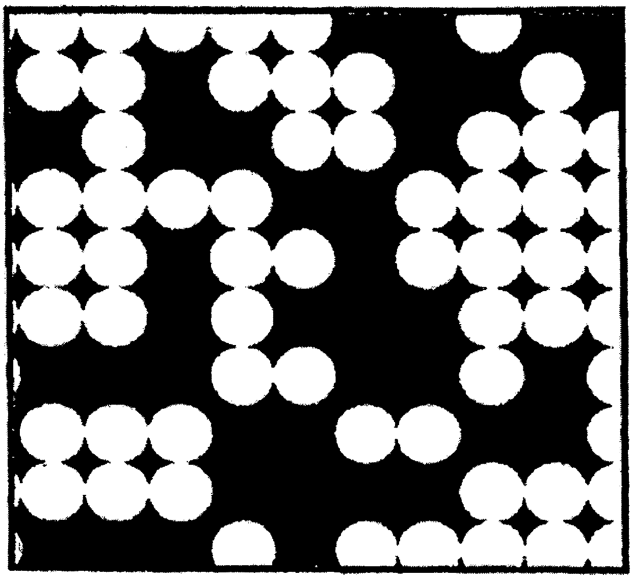
[0026]The present invention in the form of one or more exemplary embodiments will now be described. FIG. 2 illustrates a portion of a pattern 10 generated according to one embodiment of the present invention. The black portions 12 represent opaque regions and the white portions 14 represent transmissive regions. As will be further described below, the pattern 10 may be used to create an apodization mask.

[0027]The pattern 10 may be created in the following manner. The pattern 10 initially includes a grid of elements or dots. The size of the grid may be 50 nm, which is a small fraction of the wavelength of visible light (about 500 nm). The shape of the elements may be, for example, round or square. It should be understood that other shapes may be used for the elements. The diameter size of circular or round elements may approximate the wavelength of light or a type of electromagnetic radiation. Based on the disclosure and teachings provided herein, a person of ordinary skill in the ar...


PUM


Abstract

A method for creating an apodization mask is disclosed. According to the method, a grid is created for the pattern. The grid includes a number of elements. Each element is processed to determine whether the element is to be made transmissive based on a predetermined local optical density and a random value. The predetermined local optical density and the random value are associated with the element. The random value is generated on a random basis. Each element is further processed to determine whether the position of the element is to be shifted. The positional shift is determined on a random basis. The grid with the processed elements is then used to make an apodization mask. The apodization mask may be used in an optical instrument, such as, an interferometer.

Description

STATEMENT AS TO RIGHTS TO INVENTIONS MADE UNDER FEDERALLY SPONSORED RESEARCH OR DEVELOPMENT[0001]This invention was made with government support under Contract No. FGHEC3000 pursuant to the Space Interferometry Mission. The government may have certain rights in this invention.CROSS-REFERENCES TO RELATED APPLICATION(S)[0002]Not Applicable.BACKGROUND OF THE INVENTION[0003]The present invention relates generally to optical processing, and more specifically, to improved optical processing using an apodization mask.[0004]Apodization masks are employed to softly shape an optical beam in optical instruments, such as, an interferometer. One purpose of using such masks is to prevent diffraction rings from being generated due to hard edge clipping. Hard edge clipping might create interfering signals that can degrade the resulting metrology measurement. FIG. 1 is a simplified schematic diagram illustrating a portion of a pattern used in a conventional apodization mask.[0005]Normal apodization ...

Claims


Application Information

Patent Timeline
IPC IPC(8): G06F17/50
CPCG03F7/70091G02B27/58G03F7/70191
Inventor SOMERSTEIN, STEPHEN F.REALE, MARTINA J.
Owner LOCKHEED MARTIN CORP
Features
  • Generate Ideas
  • Intellectual Property
  • Life Sciences
  • Materials
  • Tech Scout
  • Unparalleled Data Quality
  • Higher Quality Content
  • 60% Fewer Hallucinations
Learn More