Disconnect switch arc eliminator

a technology of disconnection switch and arc eliminator, which is applied in the direction of circuit-breaking switch details, switches with movable electrical contacts, electrical apparatus, etc., can solve the problems of arc so intense, switch destruction, and the entire power section must be killed

Inactive Publication Date: 2013-04-09
WHITE PAUL F
View PDF7 Cites 13 Cited by
  • Summary
  • Abstract
  • Description
  • Claims
  • Application Information

AI Technical Summary

Benefits of technology

[0034]With pressure bolted disconnect switches the gate contact is not used for the primary blade and a gate contact is utilized at the switch side operating handle so that as the handle / operating mechanism is actuated, the gate contact is activated and the contact allows voltage to pass through it in the same manner as the primary blade gate contact and the IGBT device is turned on before blade movement commences and prior to release of pressure on the primary jaw. As the handle / operating mechanism is further moved, engagement to jaw pressure linkage is released so that the connection between the jaw and blade is relaxed and a loose fit to allow blade opening movement can occur without any arcing.
[0035]By turning on the IGBT prior to relaxation of jaw pressure, arcing between the jaw and blade is eliminated because current can flow from the blade through the secondary jaw to the IGBT to the load side cable.

Problems solved by technology

This becomes problematic in that the entire power section must be killed in order for the switch to be operated, affecting other operations on the railway system.
In the closing of pressure bolted disconnect switches the same problem of arcing is encountered as the blade, when seated in the jaw, initially experiences a loose fit and, if the power section feeding the switch is energized (alive), arcing will occur in the closing process until the mechanical linkage can press the jaws tight against the blade.
The continuation of arcing is analogous to welding and current will continue to flow and the load side of the power section will remain alive until there is enough metal melted away from burning to create a sufficient gap length which will cause cessation of the arc with resulting switch destruction.
When the 180 degree non-load break switch is opened under full load capacity for which the switch assembly is designed and carrying its rated current in the closed position, which on electric railways, electric trolley bus systems, mine operations, or DC motor control can be typically up to 4,000 amperes, the arc is so intense and of such magnitude that an explosion ensues and severely damages the equipment.
Due to the severe burning that takes place, these types of load break switches have limited amounts of operational sequence openings under load where, when they reach their limit of openings under load, burnt out arc extinguishing components and switch parts must be replaced.
For non-load break switches which must be operated with a high current load of varying magnitude, the electrical circuit is typically killed at the source by opening substation circuit breakers to stop the flow of electrical current through the switch.
There is also the possibility of internal component breakdown so that the controlling circuit that turns the device on or off can break down due to heat or voltage spikes and turn the device on or the device can short circuit and cause the power section to become alive.
These possibilities make electronic switching devices potentially unsafe.
With no observable physical break, they are not suitable for use in the killing of power sections when protection to human life is critical.
The method for arc suppression as applied by Hongel does not prevent arcing as the MOSFET is not turned on prior to opening of the switch S1 and arcing occurs.
It also does not provide a physical break between DC supply 6 and load 8 when the switch S1 is open.
The circuit components in 10 can short circuit and break down due to heat or electrical insulation breakdown and not provide fail safe operation.

Method used


Image

  • Disconnect switch arc eliminator
  • Disconnect switch arc eliminator
  • Disconnect switch arc eliminator

Examples


Embodiment Construction

)

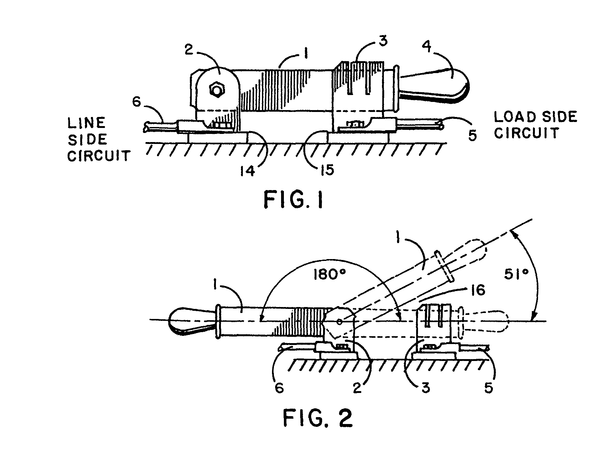
[0060]Referring to FIG. 1 there is shown the preferred embodiment of the invention applied to a disconnect switch as would be found in an electric railway, electric trolley bus system, mining operation or with motor control apparatus.

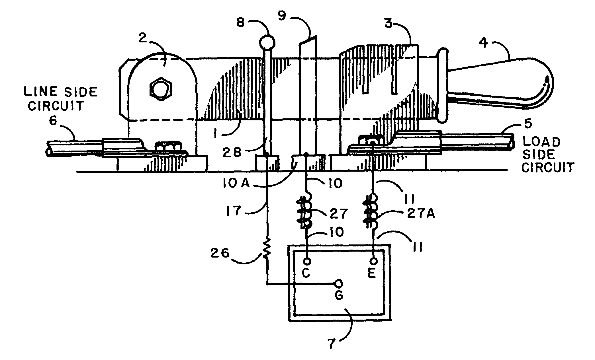
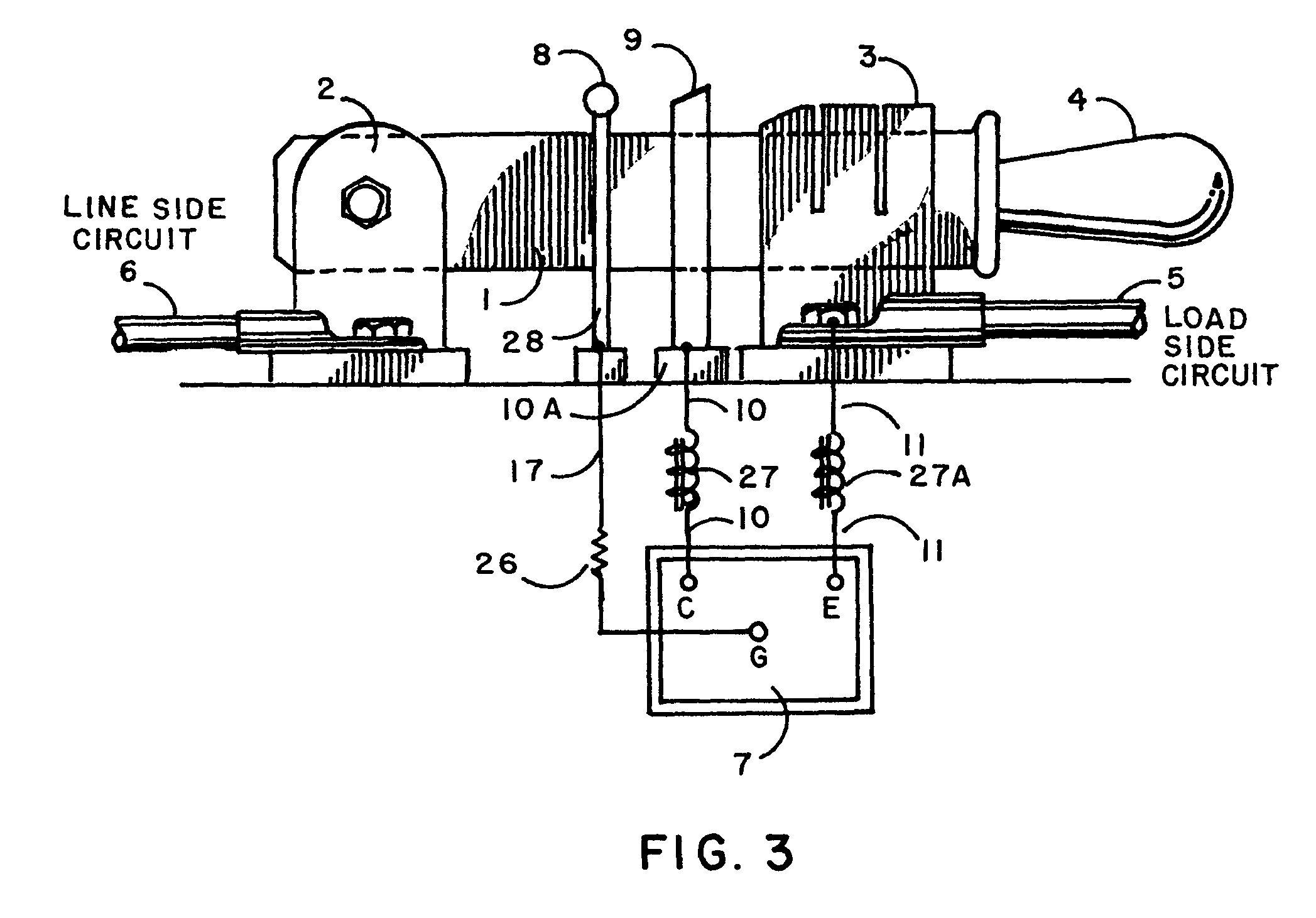
[0061]The following components of the equipment are shown in FIG. 3: primary blade 1 of the switch assembly, hinge 2 on hinge insulated mounting block 14 to which primary blade 1 is attached, primary jaw 3 into which primary blade 1 inserts, such primary jaw 3 mounted on jaw insulated mounting block 15, switch handle 4, primary jaw cable (load side circuit) 5, hinge cable (line side circuit) 6, insulated gate bipolar transistor (IGBT) 7, gate contact 8 held by gate contact support 28 attached to gate contact wire 17, secondary jaw 9, secondary jaw connection cable 10, secondary jaw insulated base 10A, choke coil 27, primary jaw connection cable 11, and choke coil 27A. The operation and function of the various components described in terms of the operat...


PUM


Abstract

A device that allows standard non-load break disconnect switches to become full load break disconnect switches in that they can interrupt high levels of their rated current with no arcing or burning when the switch is opened under load in direct current use on electric railways, electric trolley bus systems, mine operations and motor controls.

Description

[0001]This application claims priority and benefit of a provisional patent application entitled Disconnect Switch Arc Eliminator, Application No. 61 / 211,032 filed Mar. 26, 2009, now pending.BACKGROUND OF THE INVENTIONDescription of the Prior Art[0002]Non-load break switches are devices that physically break an electrical circuit by being operated from a closed position to an open position. They typically consist of a blade that is attached to a hinged support in such a manner that the blade can rotate from 0 degrees or any intermediate in-between angle, typically 51 degrees to 180 degrees in the open position. When in the closed position at 0 degree, the blade typically makes contact with a jaw support by inserting itself into the jaws of said jaw support.[0003]Both load break and non-load break disconnect switches physically disconnect an electrical circuit by being operated where the blade is placed in either a 51 degree, a 180 degree or some other angle in the open position so th...

Claims


Application Information

Patent Timeline
Patent Type & Authority Patents(United States)
IPC IPC(8): H01H73/18
CPCH01H9/542H01H31/28H01H1/42
Inventor WHITE, PAUL F.
Owner WHITE PAUL F
Why Eureka
Try Eureka