Eureka AIR delivers breakthrough ideas for toughest innovation challenges, trusted by R&D personnel around the world.

Large-scale biomass power generation process

A biomass power generation and biomass technology, applied in the field of biomass, can solve the problems of high unit power generation investment, excessive tar content, high production cost, etc., and achieve the effects of less spare parts and maintenance, low production cost, and small heat loss

Inactive Publication Date: 2018-01-05
许志英
View PDF4 Cites 2 Cited by
  • Summary
  • Abstract
  • Description
  • Claims
  • Application Information

AI Technical Summary

Problems solved by technology

The main disadvantages of the current biomass direct combustion power generation process are: small power generation scale (maximum 50,000 KW), high unit power generation investment
The main disadvantages of the current biomass gasification power generation process are: the tar content in the gas exceeds the standard, the power generation scale is too small (maximum 5000KW), and the production cost is high

Method used


Image

  • Large-scale biomass power generation process
  • Large-scale biomass power generation process

Examples


Embodiment 1

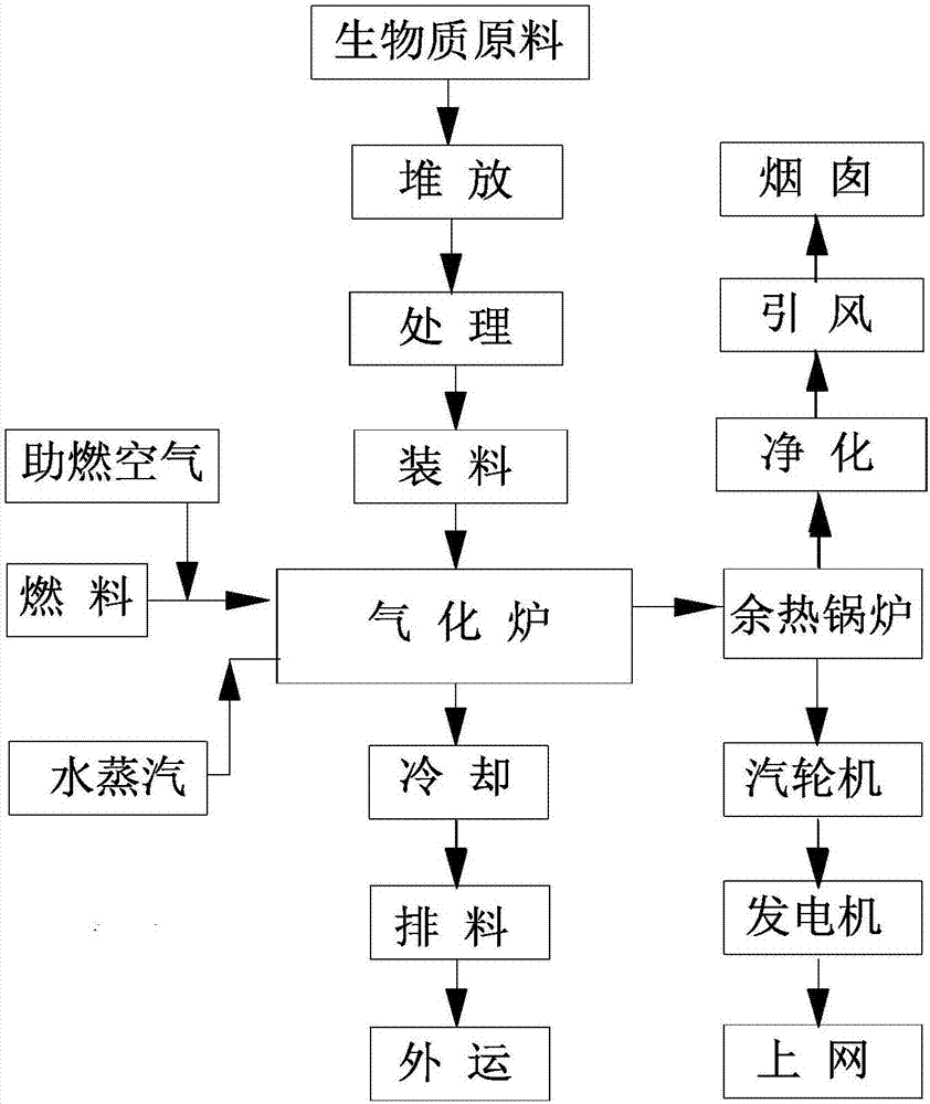
[0036] Such as figure 1 As shown, the present invention provides a kind of large-scale biomass power generation process, and its main production steps include:

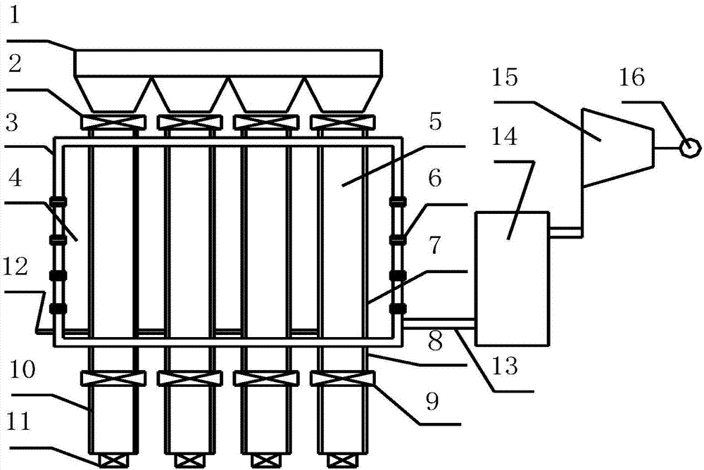
[0037] 1) All kinds of straw (including corn straw, sorghum straw, etc.) are transported to the yard for classification and storage, after shearing (the longest size is controlled within 100mm) and drying, they are transported to the furnace of the gasifier through a hopper The top is loaded into the feeding bin first, and then loaded into the gasification tank of the gasifier through the feeding device;

[0038] 2) The size of the gasification tank is a tank body with a width of 630mm, a length of 1600mm, and a height of 8000mm. It can hold about 800kg of straw, and each tank can process about 400kg of straw per hour. The annual processing capacity of one tank is about 3360t, and 50 tanks per year The biomass treatment capacity reached 168,000 tons;

[0039] 3) The heat generated by combustion in the combustion ch...

Embodiment 2

[0049] Such as figure 1 As shown, the present invention also provides a large-scale biomass power generation process, the main production steps of which include:

[0050] 1) All kinds of wood (including willow, pine, etc.) are transported to the storage yard for classification and storage. After shearing, crushing (the maximum size is controlled within 100x100x100mm) and drying, etc., they are transported to the gasification pyrolysis through the transportation device The top of the furnace is first loaded into the feeding bin, and then loaded into the gasification and pyrolysis tank of the gasification and pyrolysis furnace through the feeding device;

[0051] 2) The size of the gasification pyrolysis tank is a tank body with a width of 630mm, a length of 1600mm, and a height of 8000mm, which can accommodate about 1600kg of wood blocks. Each tank can process about 800kg of wood blocks per hour, and the annual processing capacity of one tank is about 6720t, 208 The annual bi...


PUM


Abstract

The invention relates to a large-scale biomass power generation process which comprises the following steps: after being stacked in a storage yard, a biomass is added in a biomass gasification furnaceby charging equipment through processing treatment; the biggest characteristic of the furnace is that a combustion chamber for providing heat and a gasification tank are relatively-independent spaces, and the heat in the combustion chamber is transferred to the gasification tank through a partition wall. After the pyrolysis and the gasification of the biomass are finished in the gasification tank, gas enters the combustion chamber for combustion, generated high-temperature flue gas is produced into steam through a waste heat boiler, and the steam drives a steam turbine to generate power. Compared with an existing biomass power generation process, the large-scale biomass power generation process provided by the invention has the significant advantages of being wide in raw material adaptability, large in handling capacity, high in environmental protection, low in investment, low in cost and the like.

Description

technical field [0001] The invention relates to the technical field of biomass, in particular to a biomass power generation process, aiming to realize power generation through pyrolysis and gasification of biomass. Background technique [0002] Biomass refers to various organisms produced through photosynthesis by using the atmosphere, water, land, etc., that is, all living and growing organic substances are collectively referred to as biomass, including all plants, microorganisms, and plants and microorganisms that feed on plants and microorganisms. Animals and their wastes, such as crops, crop waste, wood, wood waste, animal manure, domestic garbage, domestic sewage, etc. Representative biomass includes various straws, wood, rice husks, peanut shells, Corncobs, seaweed, bagasse, straw, weeds, manure and various organic domestic waste, construction waste or industrial waste, etc. [0003] The main characteristics of biomass are: renewable, low pollution, very rich in total...

Claims


Application Information

Patent Timeline
IPC IPC(8): C10J3/72
CPCY02P20/129
Inventor 许志英
Owner 许志英
Why Eureka
Eureka Blog
Learn More