Laser diode combiner modules

a technology of laser diodes and combiners, applied in the field of laser diode assemblies, can solve the problems of difficult beam combining, asymmetry complicating beam combining optics, and more difficult cooling, so as to reduce thermal impact, reduce thermal stability, and reduce the effect of thermal impa

Inactive Publication Date: 2013-04-30
FAYBISHENKO VICTOR
View PDF35 Cites 34 Cited by
  • Summary
  • Abstract
  • Description
  • Claims
  • Application Information

AI Technical Summary

Benefits of technology

[0012]The inventor has observed that in order to provide stable alignment between the laser diodes and the optical components, it is desirable to “thermally isolate” the optical paths of the diodes' output beams 112 in the sense that thermal degradation of the path of any one beam 112 should preferably have a minimal effect on the other beams 112. Thus, for any beam 112, the alignment between the corresponding laser diode and the corresponding optical components (e.g. FAC, SAC, and a beam-redirecting mirror) should remain stable with temperature and should not be affected by the other diodes and optical components.
[0014]We will use the term “single diode subassembly” to denote a heat-dissipating surface region with its diode chip, FAC, SAC, beam-redirecting mirror, and the respective submounts. In some embodiments, the cooling path from each single-diode subassembly is downward. The single diode subassemblies (and in particular their beam-redirecting mirrors) are laterally offset from each other so as to reduce the thermal impact of one single-diode subassembly on the downward cooling path of any other single-diode subassembly. (Of note, in FIGS. 1A-1C, the beam-redirecting mirrors 140 of one pair of diodes 110 are located one above the other, and SAC 134 is shared by the laser diodes; in FIGS. 2A-2F, SAC 134 for one laser diode 110 is located in subassembly 204 holding another diode 110.) In some embodiments, high thermal stability is provided, with near diffraction-limited beam-quality output.
[0015]In some embodiments, even though the mirrors do not overlie each other as in FIGS. 1A-1C, each beam 112 has a small optical path length. The optical path length is affected by the distance (the pitch) between adjacent laser diode chips 110 on each given side of the combined beam. The minimal acceptable pitch may have to be large to ensure adequate heat dissipation (e.g., the size of each submount can be large). However, the pitch between mirrors 140 can be smaller since the mirrors' heat dissipation requirements are lower than for the diodes. In some embodiments, the pitch between the mirrors is about one half of the pitch between the diodes. To avoid brightness and power losses, the length of the slow axis of each beam 112 after collimation is set to be less than one half of the pitch between the diodes. Due to the small pitch between the mirrors, the module's dimension along the combined beam is small, and hence the optical path length of the longest beam 112 is small. Small optical path length is desirable because the beams 112 diverge slightly even after collimation, and the divergence reduces the output brightness.

Problems solved by technology

However, beam combining for laser diodes is challenging because an individual diode's output beam is asymmetric, being elongated along the diode's pn junction.
This asymmetry complicates beam-combining optics.
In addition, the small size of laser diodes makes cooling more difficult.
Further, heat causes degradation of the diodes' slope efficiency (i.e. the efficiency in converting electrical energy to light).
However, multiple-emitter diode chips are less reliable than single-emitter diode chips because the multiple-emitter diode chips are harder to cool in uniform manner.
Also, a diode's failure in a multiple-emitter chip can affect other diodes in the chip, so the entire chip can become unusable if a single diode fails.
Of note, compact size and effective cooling are mutually conflicting goals, and effective cooling is especially challenging when the number of diodes is large.
Therefore, designing a module that is optimized for maximum brightness of the combined beam, maintains near diffraction limited quality output, is compact in size, provides uniform thermal conditions for all laser diodes, and scalable (from a few diodes to maybe thousands of diodes) is generally a difficult challenge.
Therefore, non-uniform distribution of the laser diodes above this interface could lead to non-uniform thermal conditions of different laser diodes and hence to loss of spectral brightness.
Due to thermal stability and low thermal resistance of the individual modules, the thermally induced spectral shift is small, and the beam formed of the combined output beams of the individual modules has near diffraction-limited beam quality.

Method used


Image

  • Laser diode combiner modules
  • Laser diode combiner modules
  • Laser diode combiner modules

Examples


Embodiment Construction

[0038]The embodiments described in this section illustrate but do not limit the invention. For example, the inventions is not limited to particular dimensions and spatial arrangements except as defined by the appended claims. The features described as “horizontal” or “vertical” refer to a particular spatial orientation. However, neither the invention nor its embodiments are limited to any particular spatial orientation in manufacture, use or operation unless noted otherwise.

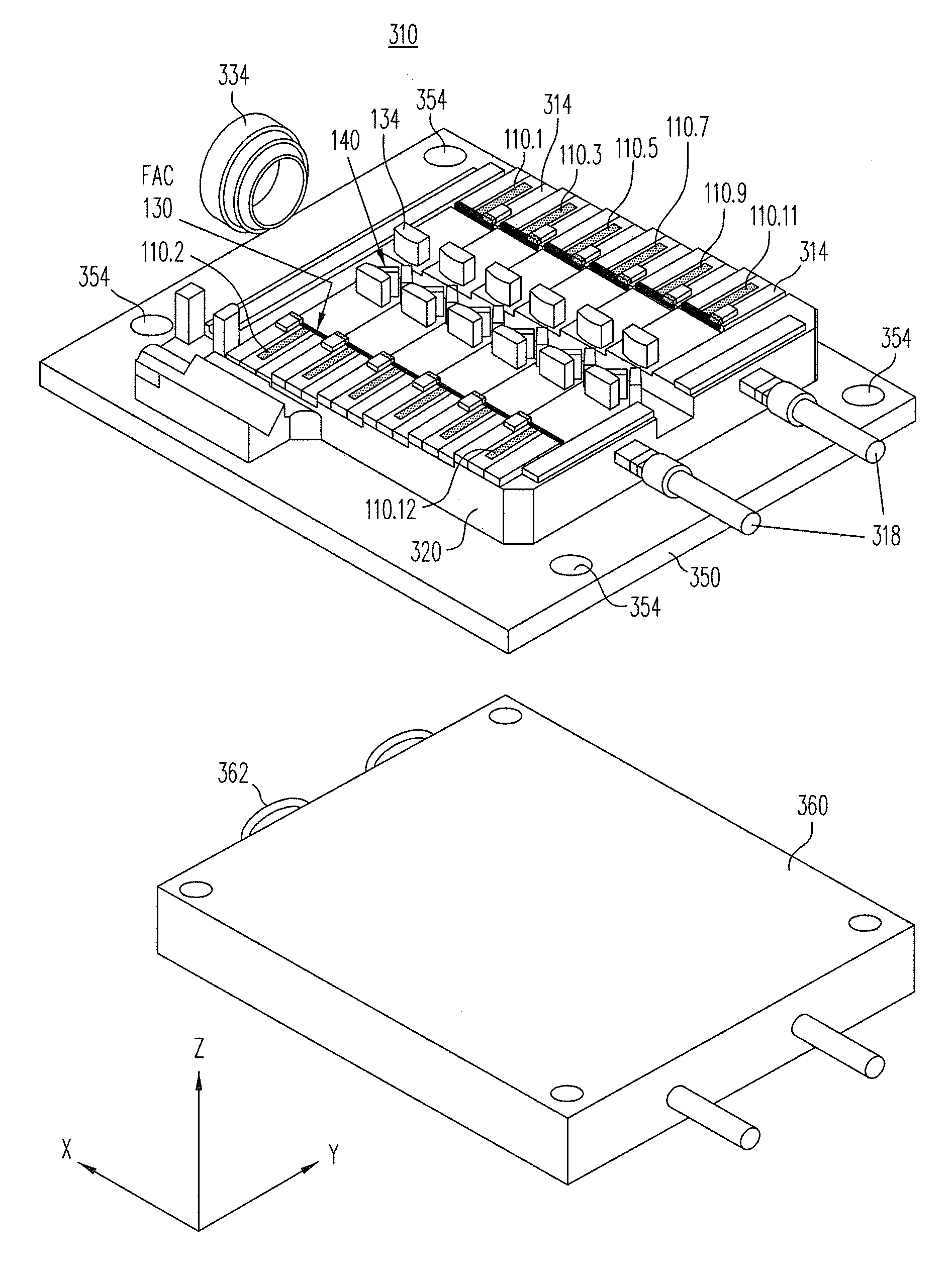
[0039]FIGS. 3A-3D, 4A-4B, and 5A-5B illustrate a laser assembly (laser module) 310 according to some embodiments of the present invention. FIG. 3A is a three-dimensional view; FIG. 3B is a top view; FIG. 3C is a side view; FIG. 3D is a three-dimensional, cross-sectional view showing a vertical cross section along the line D-D′ shown in FIG. 3B; FIGS. 4A, 4B, and 5A-5B are top views like FIG. 3B but showing some additional features.

[0040]Module 310 includes 12 single-emitter laser diode chips 110.1-110.12. Each di...


PUM


Abstract

In a laser module (310), single-emitter laser diode chips (110) are positioned at different heights on opposite sides of the module's combined output beam (114). Each laser diode chip (110), and its corresponding fast and slow axis collimators (130, 134), and turning mirror (140) are positioned on a corresponding heat-dissipating surface region (340). High thermal stability and output power are obtained in some embodiments even if the modules are combined to obtain higher-level modules (310-2). Other features and embodiments are also provided.

Description

BACKGROUND OF THE INVENTION[0001]The present invention relates to laser diode assemblies (laser diode modules) which combine output beams emitted by single-emitter laser diode chips.[0002]Diode lasers are compact, inexpensive to manufacture, and easy to service compared to many other types of lasers. An individual laser diode has a fairly low output power (typically from hundreds of milli-Watt to several Watt), but laser diodes can be combined to obtain a high-power beam, e.g. in kilo-watt range. When laser diode beams are combined, the combined beam should preferably be high in brightness and power, and have near diffraction-limited beam quality. However, beam combining for laser diodes is challenging because an individual diode's output beam is asymmetric, being elongated along the diode's pn junction. The beam's divergence is also asymmetric—the divergence is lower along the “slow” axis parallel to the pn junction than along the “fast” axis perpendicular to the pn junction. (The ...

Claims


Application Information

Patent Timeline
Patent Type & Authority Patents(United States)
IPC IPC(8): H01S3/04G02B27/20
CPCG02B6/4296G02B19/0028G02B19/0057
Inventor FAYBISHENKO, VICTOR
Owner FAYBISHENKO VICTOR
Why Eureka
Try Eureka