Methods and systems for supporting a workpiece and for heat-treating the workpiece

a technology of workpieces and supports, applied in the direction of electrolysis components, manufacturing tools, shaping tools, etc., can solve the problems of large downward force applied to the edges of the wafer, damage to the wafer, and insufficient deformation of the wafer, so as to effectively short effectively lengthen the unconstrained portion

Active Publication Date: 2013-05-07
MATTSON TECHNOLOGY +1
View PDF299 Cites 7 Cited by
  • Summary
  • Abstract
  • Description
  • Claims
  • Application Information

AI Technical Summary

Benefits of technology

[0013]The present invention addresses the above needs by providing, in accordance with a first aspect of the invention, a method of supporting a workpiece. The method includes supporting the workpiece while allowing thermally-induced motion of the workpiece. Advantageously, by allowing the thermally-induced motion rather than attempting to prevent it, the workpiece is allowed to naturally deform into a stress-minimizing shape, thereby reducing stress in the workpiece. At the same time, by continuing to support the workpiece while allowing such thermally-induced motion, the workpiece is maintained in a desired region.
[0083]Advantageously, such heat-treating methods may serve to reduce thermal stress and suppress vibration in the workpiece, by taking advantage of the finding of the present inventors that, depending on the rapidity of the surface heating stage, the thermal bowing of the workpiece may significantly lag the temperature increase itself. For example, in one particular case, where the irradiating for the first time period was achieved by way of a heating flash of approximately one millisecond in duration, a peak temperature of the irradiated surface occurred roughly simultaneously with the end of the flash (t=1 ms). However, at that time, the wafer had only just begun to thermally bow, and had therefore achieved only a relatively small percentage of its maximum thermal bowing amplitude. The maximum thermal bowing amplitude was not achieved until nearly four milliseconds later, at which time the wafer had overshot its equilibrium shape. A short time later, at approximately t=6 ms, the wafer was still significantly bowed but was returning toward its flat position with significant return velocity. In accordance with one embodiment of the aforementioned aspect of the invention, the device side of the wafer is subjected to a second irradiance flash, timed so that the resulting thermal bowing from the second irradiance flash occurs while the wafer is already thermally bowed from the first flash and is returning toward its flat position. The stress in the wafer produced by the thermal bowing resulting from the second flash is diminished, because the wafer is already thermally bowed due to the first flash. The thermal bowing resulting from the second flash also acts in a direction opposite to the existing return velocity of the wafer as it attempts to return toward its flat position. Accordingly, the thermal bowing resulting from the second flash tends to suppress residual vibrations from the first flash. The combination of two such flash-heating stages in rapid succession allows higher peak temperatures to be achieved, while reducing residual vibrations in the wafer. The alternative use of continuous irradiance may also provide similar advantages.

Problems solved by technology

However, due to the extreme rapidity at which the device side of the wafer is heated (in the course of a 1-millisecond flash, for example, much faster than a typical thermal conduction time in the wafer), the deformation of the wafer may occur sufficiently rapidly that the edges of the wafer apply a large downward force onto the support pins that support the wafer in the chamber.
As conventional support pins are typically rigid, the resulting reaction force between the pins and the edges of the wafer may damage the wafer.
Such forces may also cause the wafer to launch itself vertically upward from the support pins, which may result in further damage to the wafer as the wafer falls back down and strikes the pins.
Also, as conventional support pins are not designed to withstand such forces, they tend to break, with the result that the wafer falls in the chamber and is damaged or destroyed.
In addition, due to the rapidity at which such thermal bowing occurs, the initial velocities imparted to the various regions of the wafer tend to cause the wafer to overshoot the equilibrium minimum stress dome shape and oscillate or vibrate, resulting in additional stress and potential damage to the wafer.
Thus, the use of conventional support systems employing rigid fixed support pins or rings imposes undesirable limitations on the magnitude of the temperature jump that can be achieved without damaging or breaking the wafer.

Method used


Image

  • Methods and systems for supporting a workpiece and for heat-treating the workpiece
  • Methods and systems for supporting a workpiece and for heat-treating the workpiece
  • Methods and systems for supporting a workpiece and for heat-treating the workpiece

Examples


first embodiment

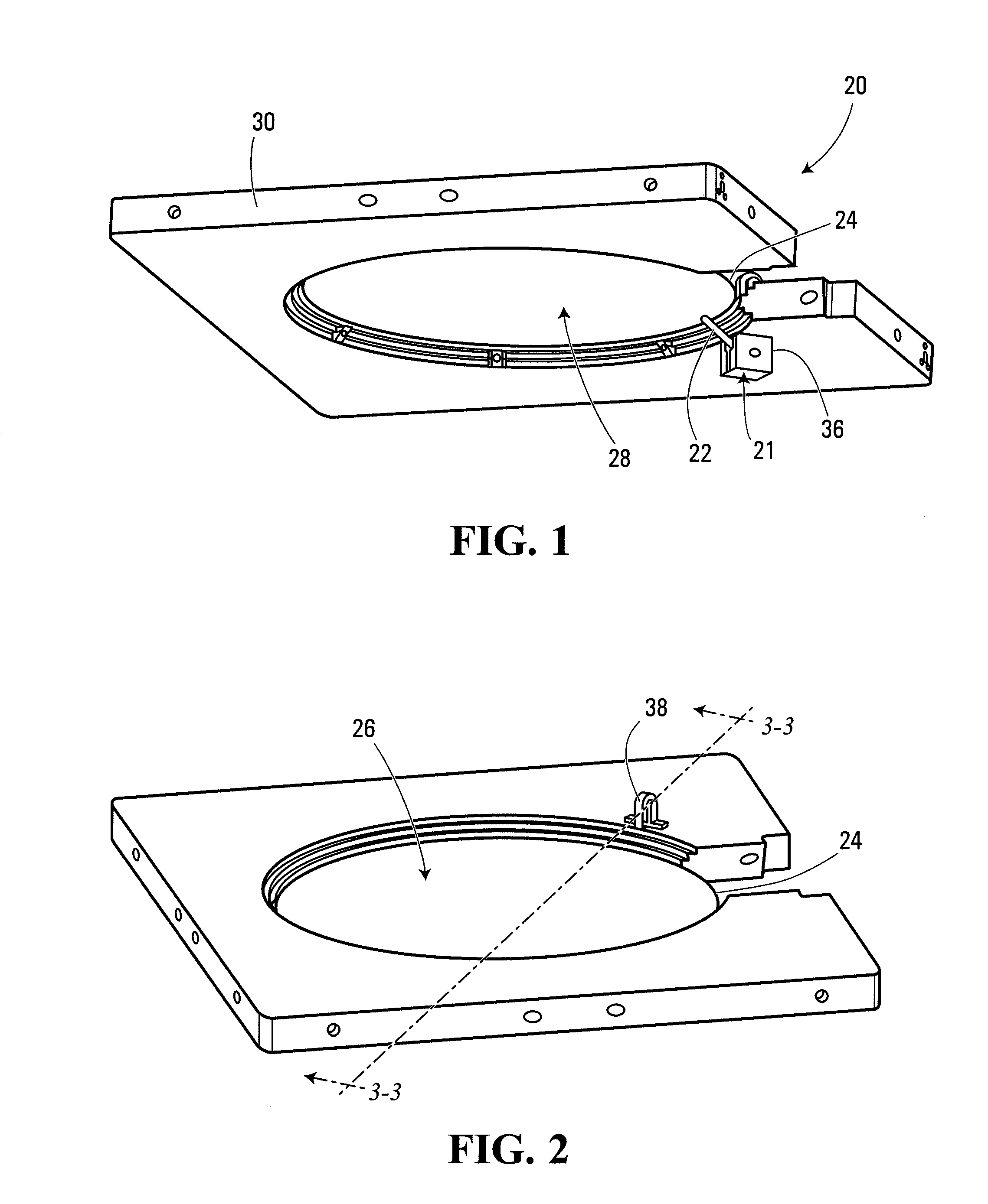
[0126]Referring to FIGS. 1-4, an apparatus for supporting a workpiece according to the invention is shown generally in FIG. 1. In the present embodiment, the apparatus includes a support system 20 configured to support a workpiece 24 while allowing thermally-induced motion of the workpiece.

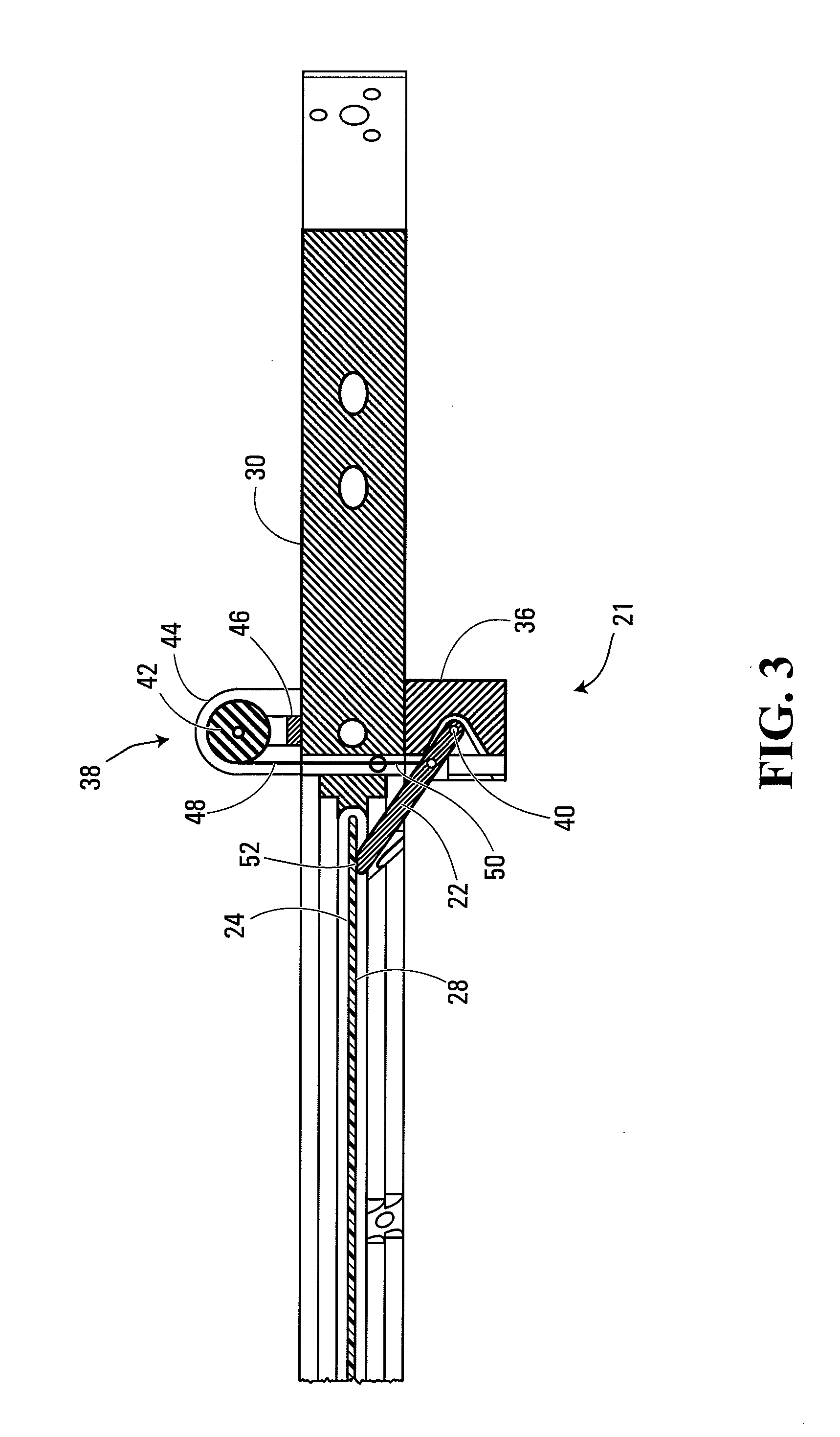
[0127]In this embodiment, the support system 20 includes a supporting device shown generally at 21. More particularly, in this embodiment the supporting device 21 includes a support member 22 engageable with the workpiece 24. More particularly still, in the present embodiment the support member 22 has a moveable engagement portion 52 shown in FIG. 3, which is engageable with the workpiece 24 and which is moveable to allow the thermally-induced motion of the workpiece while supporting the workpiece.

[0128]In the present embodiment, the moveable engagement portion 52 of the support member 22 includes a tip of the support member. In this embodiment, the support member 22 is rigid, and the moveable eng...

second embodiment

[0146]Referring to FIG. 5, a supporting device according to the invention is shown generally at 80. In this embodiment, the supporting device 80 includes a support member 82, similar to the support member 22 discussed earlier herein. In this embodiment, the support member 82 is mounted to a support member housing (not shown) at a pivot point 84, for pivotal motion thereabout. As in the previous embodiment, the supporting device 80 includes a force applicator, or more particularly a torque applicator comprising a spring 86, in communication with the support member 82 to apply a force to the support member to cause an engagement portion 88 to tend to maintain contact with the workpiece during thermally-induced motion thereof. In the present embodiment, however, the torque applicator is configured to apply a downward force at a location on the support member 82 such that the pivot point 84 of the support member 82 is interposed between the location and the engagement portion 88. More p...

third embodiment

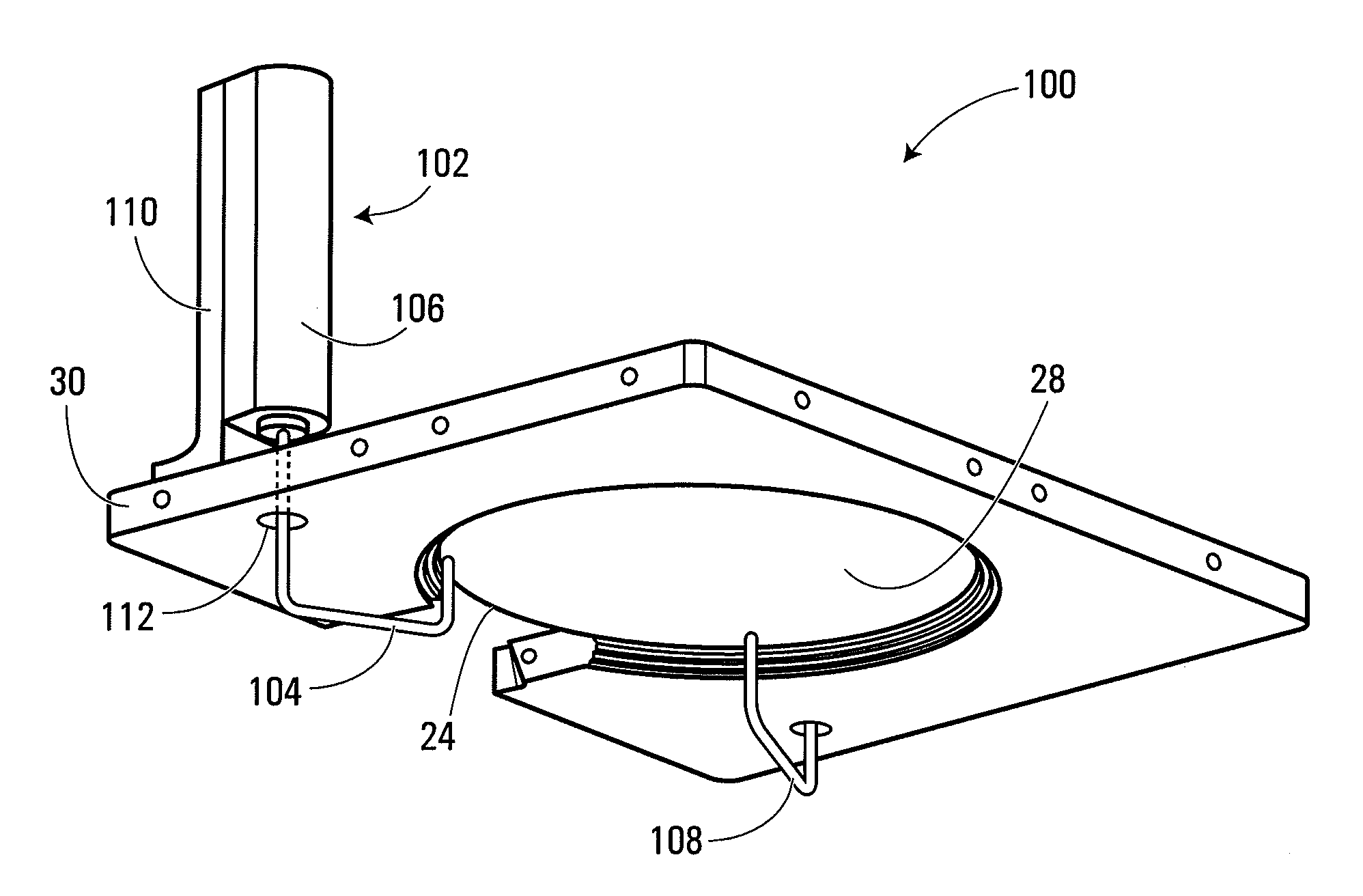
[0147]Referring to FIG. 6, a system for supporting a workpiece according to the invention is shown generally at 100. The system 100 includes a supporting device 102 configured to support the workpiece 24 while allowing thermal bowing or other thermally-induced motion of the workpiece.

[0148]In this embodiment, the supporting device 102 includes a support member 104 having a moveable engagement portion engageable with the workpiece 24. In the present embodiment, the moveable engagement portion includes a tip of the support member 104. The support member 104 is rigid, and the moveable engagement portion is moveable by virtue of the support member 104 as a whole being moveable, as described below.

[0149]In the present embodiment the support member 104 is engageable with the exclusion zone at the outer perimeter of the substrate side 28 of the workpiece. The support member 104 includes a quartz pin, for reasons similar to those discussed in connection with the first embodiment of the inve...


PUM

PropertyMeasurementUnit
distanceaaaaaaaaaa
angleaaaaaaaaaa
angleaaaaaaaaaa

Abstract

An apparatus for supporting a semiconductor workpiece includes a heating system configured to cause thermally-induced motion of the semiconductor workpiece by heating a surface of the workpiece relative to a bulk of the workpiece. The thermally-induced motion includes vertical motion of an outer edge region of the workpiece and a center of the workpiece relative to each other. The apparatus further includes a support system configured to allow the thermally-induced motion including the vertical motion of the outer edge region of the workpiece and the center of the workpiece relative to each other while supporting the workpiece.

Description

CROSS-REFERENCE TO RELATED APPLICATIONS[0001]This application is a continuation of U.S. patent application Ser. No. 10 / 742,575 filed Dec. 19, 2003, which claims the benefit of priority from U.S. patent application Ser. No. 60 / 434,670 filed Dec. 20, 2002, and from U.S. provisional patent application Ser. No. 60 / 468,659 filed May 8, 2003, all of which are hereby incorporated herein by reference.BACKGROUND OF THE INVENTION[0002]1. Field of Invention[0003]The present invention relates to methods and apparatuses for supporting a workpiece, and also relates to methods and apparatuses for heat-treating a workpiece.[0004]2. Description of Related Art[0005]Numerous applications require a workpiece to be supported. For example, in the manufacture of semiconductor chips such as microprocessors, the workpiece typically includes a semiconductor wafer, which must be supported in a thermal processing chamber for annealing or other heat-treating processes. The wafer is normally supported in the cha...

Claims


Application Information

Patent Timeline
Patent Type & Authority Patents(United States)
IPC IPC(8): B21D37/16B23H11/00B23Q1/25H01L21/00H01L21/68
CPCH01L21/68721H01L21/68757H01L21/68728H01L21/68
Inventor CAMM, DAVID MALCOLMSEMPERE, GUILLAUMEKALUDJERCIC, LJUBOMIRSTUART, GREGORYBUMBULOVIC, MLADENTRAN, TIMDETS, SERGIYKOMASA, TONYRUDOLPH, MARCCIBERE, JOSEPH
Owner MATTSON TECHNOLOGY
Why Eureka
Try Eureka