Process and apparatus for removal of oxygen from seawater
a technology of process and equipment, applied in the direction of liquid degasification, separation process, borehole/well accessories, etc., can solve the problem of difficulty in including a heater in the mixer, and achieve the effect of avoiding fouling of downstream equipmen
- Summary
- Abstract
- Description
- Claims
- Application Information
AI Technical Summary
Benefits of technology
Problems solved by technology
Method used
Image
Examples
example 1
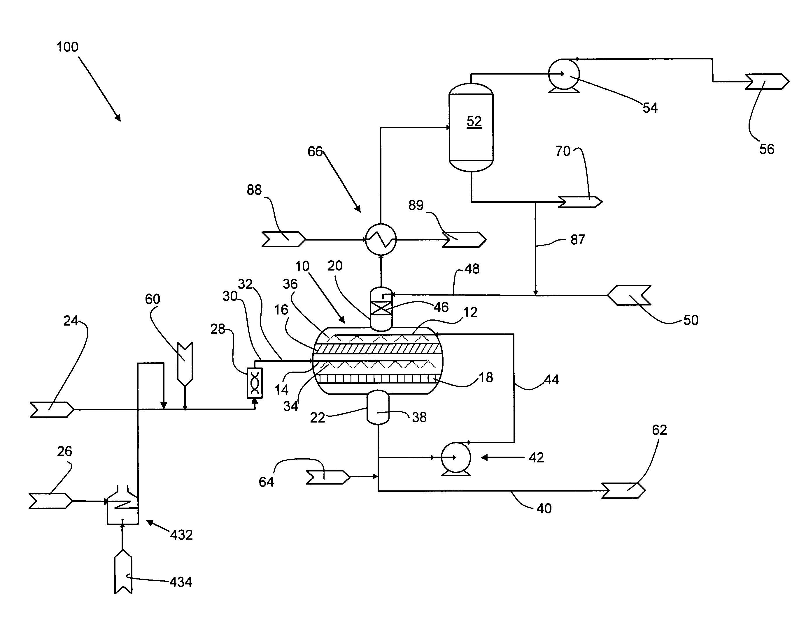
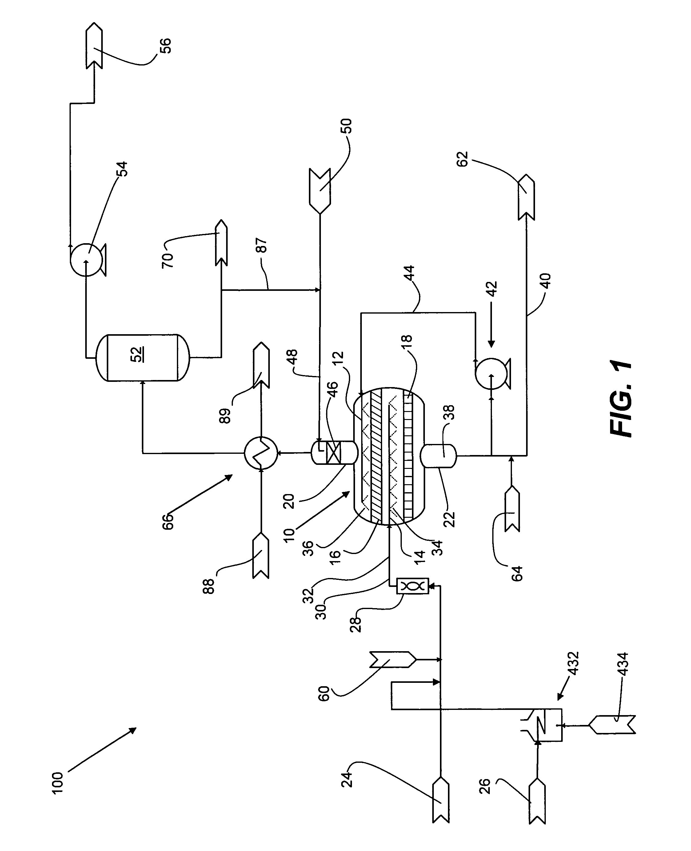
[0065]In a first case, seawater is deoxygenated in an apparatus having a single mixer and a single separator, as illustrated in FIG. 1. The feed and effluent flow rates are as shown in Table 1. The oxygen concentration in the deoxygenated seawater recovered from the apparatus is below 10 ppb.
[0066]The naturally occurring concentration of nitrogen dissolved in seawater is about 12 ppm, depending on temperature. It will be recognized that the concentration of nitrogen in seawater will change after heating and mixing with stripping gas. However, the change in concentration of nitrogen does not affect significantly the data presented below.
[0067]
TABLE 1Deoxygenation of seawater using 99.9% N2 as stripping gas at higher flow rate.Mixture ofEffluentEffluentSeawaterNitrogenseawater andgas streamliquid streamStream:feedfeedstripping gasfrom separatorfrom separatorPhase:LiquidGasMixedGasLiquidTemperature:° C.45.045.045.043.843.8Pressure:kg / cm24.04.04.00.1360.136Liquid density:kg / m3987.3987.3...
example 2
[0068]In a second case, seawater is deoxygenated under the same conditions but at a lower flow rate of both seawater and nitrogen as stripping gas. It is seen from Table 2 that the compositions of the various streams are unchanged when compared to Example 1.
[0069]
TABLE 2Deoxygenation of seawater using 99.9% N2 as stripping gas at lower flow rate.Mixture ofEffluentEffluentSeawaterNitrogenseawater andgas streamliquid streamStream:feedfeedstripping gasfrom separatorfrom separatorPhase:LiquidGasMixedGasLiquidTemperature:° C.45.045.045.043.843.8Pressure:kg / cm24.04.04.00.1360.136Liquid density:kg / m3987.3987.3987.9Mass flowkg / h662,2321,000663,2322,378660854rate:Compositions, mass percent:Water:99.9980099.847257.4070100Oxygen:0.00080.11420.00100.2706
example 3
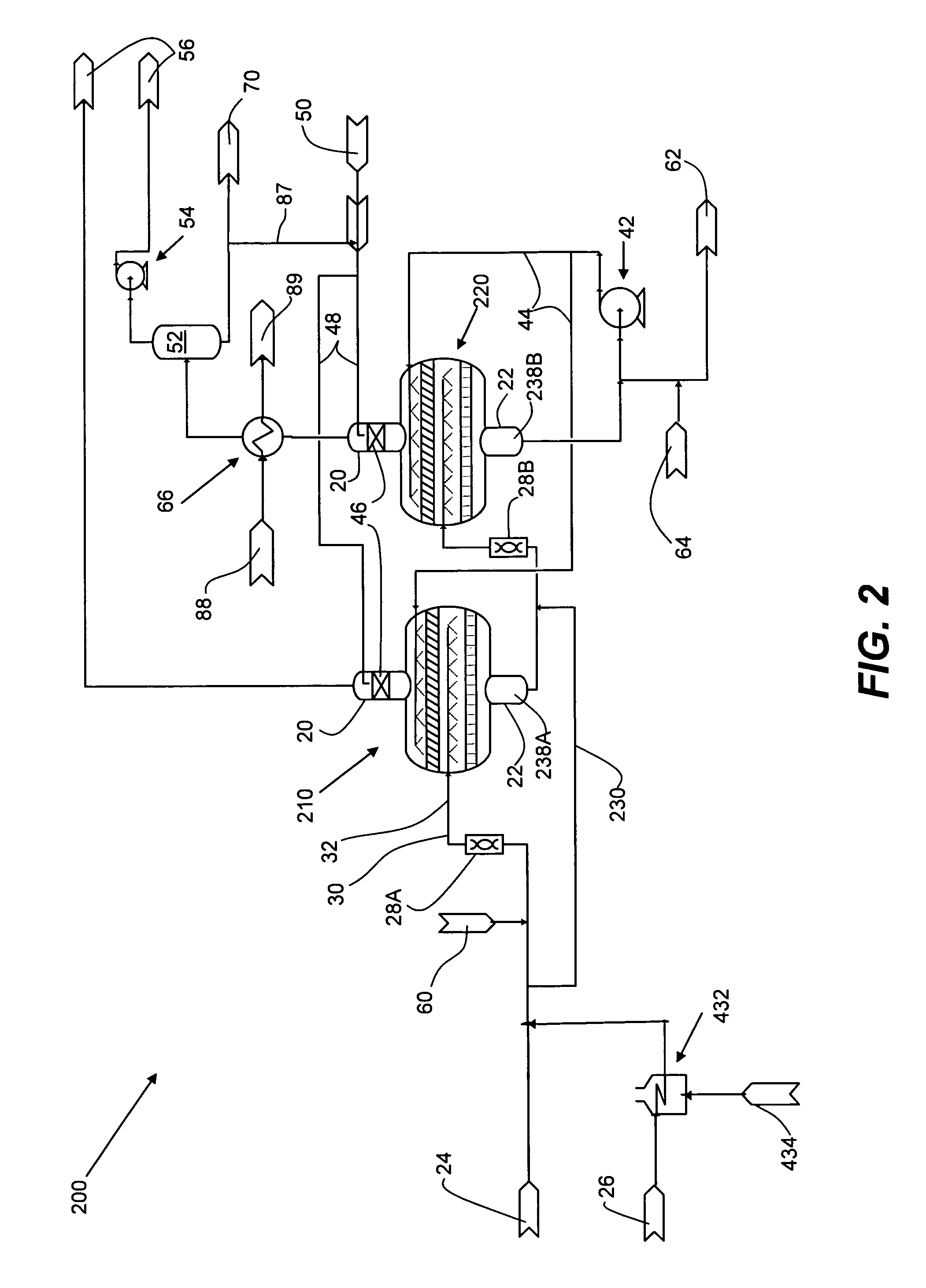
[0070]In a third case, seawater is deoxygenated in an apparatus having in sequence a first mixer, a first separator, a second mixer and a second separator, as illustrated in FIG. 2. The stripping gas is 99.4% nitrogen containing 0.6% oxygen. The feed and effluent flow rates are as shown in Table 3. It is seen that use of lower purity nitrogen as stripping gas requires use of a sequence of two combinations of mixer and separator to reduce the oxygen content of seawater below 10 ppb.
[0071]
TABLE 3Deoxygenation of seawater using 99.4% N2 as stripping gas in an apparatus having two combinations of a mixer and a separator in sequence.Mixture ofMixture ofseawater andEffluentEffluentseawater andEffluentEffluentNitrogenstrippinggas streamliquid streamNitrogenstrippinggas streamliquid streamSeawaterfeed togas fromfrom firstfrom firstfeed togas fromfrom secondfrom firstStream:feedfirst mixerfirst mixerseparatorseparatorsecond mixersecond mixerseparatorseparatorPhase:LiquidGasMixedGasLiquidGasM...
PUM
| Property | Measurement | Unit |
|---|---|---|
| pressure | aaaaa | aaaaa |
| pressure | aaaaa | aaaaa |
| temperature | aaaaa | aaaaa |
Abstract
Description
Claims
Application Information
 - R&D
- Intellectual Property
- Life Sciences
- Materials
- Tech Scout
- Unparalleled Data Quality
- Higher Quality Content
- 60% Fewer Hallucinations
Browse by: Latest US Patents, China's latest patents, Technical Efficacy Thesaurus, Application Domain, Technology Topic, Popular Technical Reports.
© 2025 PatSnap. All rights reserved.Legal|Privacy policy|Modern Slavery Act Transparency Statement|Sitemap|About US| Contact US: help@patsnap.com


