Mechanical joint for a gas turbine engine

a gas turbine engine and mechanical joint technology, applied in the direction of liquid fuel engines, screwdrivers, lighting and heating apparatus, etc., can solve the problems of inability to design and often limited strength of low thermal growth alloys at high temperatures, and achieve the effect of uniform thermal stress and controlled thermal respons

Active Publication Date: 2013-06-11
GENERAL ELECTRIC CO
View PDF19 Cites 28 Cited by
  • Summary
  • Abstract
  • Description
  • Claims
  • Application Information

AI Technical Summary

Benefits of technology

[0007]These and other shortcomings of the prior art are addressed by the present invention, which provides a multi-flange bolted joint which has controlled thermal response and uniform thermal stresses.

Problems solved by technology

However, low thermal growth alloys typically have strength limitations at high temperatures.
The LCF life can be improved by using a single integrated flange, but such a design is not always feasible because of space limitations.

Method used


Image

  • Mechanical joint for a gas turbine engine
  • Mechanical joint for a gas turbine engine
  • Mechanical joint for a gas turbine engine

Examples


Embodiment Construction

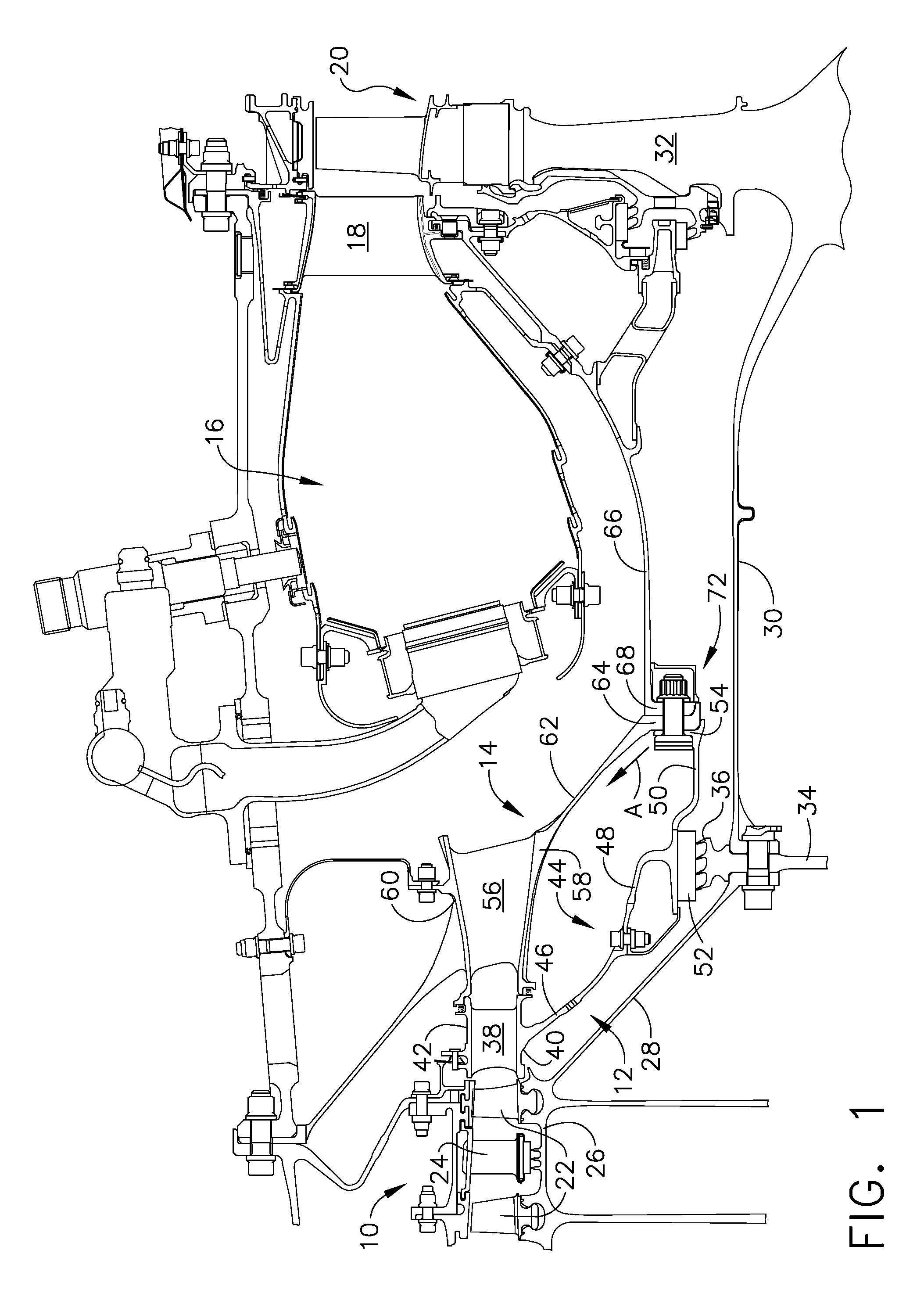
[0023]Referring to the drawings wherein identical reference numerals denote the same elements throughout the various views, FIG. 1 depicts a portion of a gas turbine engine including, generally, a high pressure compressor 10, an outlet guide vane (OGV) structure 12, a diffuser 14, a combustor 16, a turbine nozzle 18, and a high pressure turbine rotor 20. In the illustrated example, the engine is a high-bypass turbofan engine. However, the principles described herein are equally applicable to turboprop, turbojet, and turbofan engines, as well as turbine engines used for other vehicles or in stationary applications.

[0024]The compressor 10 includes a plurality of alternating stages of rotating blades 22 and stationary nozzles 24. Only the final stages of the compressor 10 are shown. The blades 22 are carried on a spool 26 which includes a shaft arm 28 that extends axially aft and radially inward. This is coupled to a turbine shaft 30 which is part of a turbine rotor disk 32. A seal dis...


PUM


Abstract

A mechanical joint for a gas turbine engine includes:(a) an annular first component having an annular, radially-extending first flange; (b) an annular second component having an annular, radially-extending second flange abutting the first flange; (c) a plurality of generally radially-extending radial channels passing through at least one of the first and second flanges; (d) a plurality of generally axially-extending channels extending through the first flange and communicating with respective ones of the radial channels; and (e) a plurality of fasteners clamping the first and second flanges together.

Description

BACKGROUND OF THE INVENTION[0001]This invention relates generally to gas turbine engines and more particularly to apparatus and methods for thermal management of mechanical joints in such engines.[0002]A gas turbine engine includes a turbomachinery core with a primary gas flowpath passing serially through a high pressure compressor, a combustor, and a high pressure turbine. The core is operable in a known manner to generate a primary gas flow. In a turbojet or turbofan engine, the core exhaust gas is directed through an exhaust nozzle to generate thrust. A turboshaft engine uses a low pressure or “work” turbine downstream of the core to extract energy from the primary flow to drive a shaft or other mechanical load.[0003]It is generally desired to seal off the primary flowpath to prevent leakage of high-pressure, high-temperature gases, so as to avoid damage to temperature-sensitive components outside the primary flowpath, for example stationary structural members, and efficiency los...

Claims


Application Information

Patent Timeline
Patent Type & Authority Patents(United States)
IPC IPC(8): F01D9/04F01D25/12
CPCF01D9/041F01D11/001Y10T403/645F16B2200/506F01D11/00F01D25/243
Inventor JASKO, RYAN MICHAELSEITZER, KENNETH EDWARDINTEMANN, PAUL ALEXANDERMUTHASAMY, SASIKUMARMONTTINEN, JARMO TAPANI
Owner GENERAL ELECTRIC CO
Why Eureka
Try Eureka