Method and device for controlling a rock drill rig

a rock drill rig and control device technology, applied in the field of rock drill rig control device, can solve the problems of loosened drill string joint, reduced productivity, and ultimately drill string breakag

Active Publication Date: 2013-06-18
EPIROC ROCK DRILLS AB +1
View PDF13 Cites 53 Cited by
  • Summary
  • Abstract
  • Description
  • Claims
  • Application Information

AI Technical Summary

Benefits of technology

[0022]In each mode, the settings are also tuned to each other such that the settings co-act and do not counter-act each other, which could otherwise easily be the case with manually set systems. For example, a high percussion pressure together with low feed force could be harmful to the equipment in certain conditions. I.a. such unwanted combinations can be avoided through the invention.
[0030]In the case of anti-jam function, the rotation pressure to the rotation motor as a rule will be increased when the drilling machine is on its way to get stuck, since a higher torque then is required in order to rotate the drill bit.
[0033]In an alternative drilling control function envisaged by the applicant, a combination of pressure and flow control of the feed flow to the feed motor is provided in order to provide a more gentle and more responsive control when the drilling machine is on its way to get jammed. This function could be initiated when the rotation pressure increases above a first level, which could be a set empirically determined value of the parameter indicating that the rotation torque and thereby the rotation resistance increases above values that can be considered to correspond to normal rock drilling. Since this reduces the feed flow will function be best suited for medium and soft rock.

Problems solved by technology

Feed pressure; too high can result in deviating drilling direction—too low can result in wear, loosened drill string joints and ultimately drill string breakage.
Percussion pressure; too high can result in wear and breakage, increased reflexes through the drill string—too low results in reduced productivity.
Rotation speed; too high can result in wear and sometimes deviating drilling direction—too low results in wear and reduced productivity.
Feed speed and feed control levels, Too high can result in damaged equipment if the drill bit enters a cavity during drilling; Too low results in reduced productivity.
Damping pressure control levels; Too high levels will result in reduction productivity because the percussion pressure is reduced to collaring level too often; Too low will result in wear and breakage.
Flushing medium pressure; Too thigh will result in wear of the drill bit and high consumption of energy; Too low results in that the drill bit gets stuck.
A problem with manual setting of parameters is that it is very complex to correctly provide a modern drill rig with the accurate % parameter settings, since altering one parameter can affect the conditions for one or a plurality of other parameters.
Lack of such balance because of altered rock formation conditions may more easily lead to jamming problems.
It can thus be very difficult even for a skilled technician or operator with great knowledge about the function of the system to obtain good results.
Most often a trail and error method has to be performed, which can be very time-consuming.
A consequence of this is that there are often no new adjustments made at all or that the rig is set such that operation will not be as efficient as it could have been.
This could lead to either increased wear and / or unnecessary ineffective operation.
For example, a high percussion pressure together with low feed force could be harmful to the equipment in certain conditions.
This function works well in hard rock but can be directly unsuitable in soft rock.
Boosted rotation, which can be useful in soft rock but unsuitable in hard rock because of increased bit wear.

Method used


Image

  • Method and device for controlling a rock drill rig
  • Method and device for controlling a rock drill rig
  • Method and device for controlling a rock drill rig

Examples


Embodiment Construction

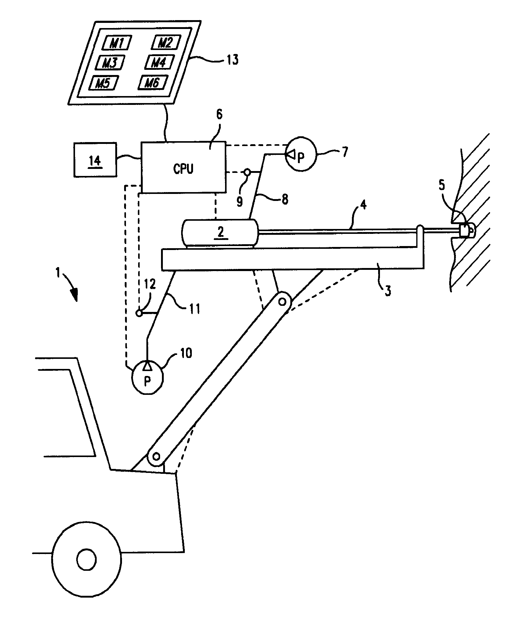
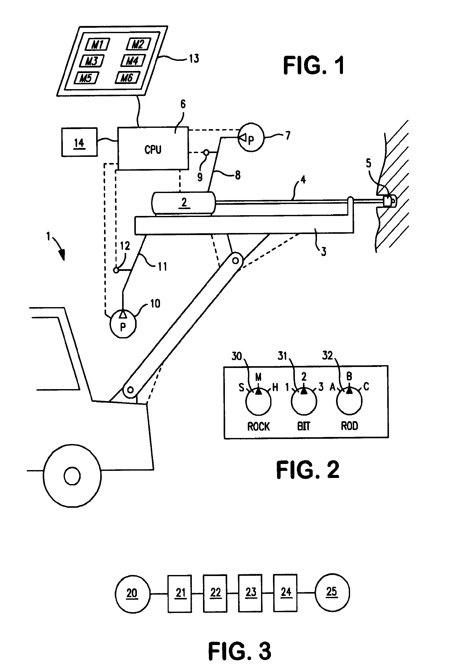
[0048]In FIG. 1, reference numeral 1 indicates a drill rig for rock drilling, having an arm carrying a feed-beam 3. On the feed-beam 3 is, as conventionally, supported a to and fro movable rock drilling machine 2, which acts on a drill rod 4, which on its distal end is provided with a drill bit 5.

[0049]The rock drilling machine 2 includes in a manner known per se a rotation device (not shown) for rotating the drill rod 4 during drilling. A rotation motor is hydraulically driven by a rotation fluid flow emanating from the pump 7 over the conduit 8. The pressure in the conduit 8 is the rotation pressure which is sensed by a pressure sensor 9.

[0050]The rock drilling machine 2, is driven with a feed force F in its forward motion by a feed motor (not shown) being hydraulically driven by a feed flow which is generated by a pump 10 and transmitted over a feed conduit 11. The pressure in the feed conduit 11 is the feed pressure which is sensed by a pressure sensor 12. Reference numeral 6 in...


PUM


Abstract

A method and a device for controlling a drill rig (1) which includes a carrier vehicle with at least one feed-beam (3), wherein a drill machine (2) is movable to-and-fro, wherein rig parameters are set by a control unit (6) and wherein each one of a plurality of operating modes (M1-M6) includes specified operating settings for different operating parameters of the rig. Each operating mode (M1-M6) is selectable such that operation of the rig is related to a particular type of rock, in which drilling is to be performed, and each operating mode (M1-M6) includes operating settings that are adapted to the prevailing type of rock. The invention also concerns a drill rig.

Description

FIELD OF THE INVENTION[0001]The invention concerns a method and a device for controlling a rock drill rig which includes a carrier vehicle with at least one feed-beam, whereon a drilling machine is movable to and fro, wherein parameters for drill rig control are set by a control unit, and wherein each one of a plurality of operating modes includes specified operating settings for different operating parameters of the rig.BACKGROUND OF THE INVENTION[0002]When performing percussive rock drilling, a shock wave is generated by the percussive mechanism of the drilling machine. This shock wave is transmitted as an energy stress wave through the drill rod down to the drill bit. When the stress wave reaches the drill bit, its hard metal button elements are pushed against the rock with such a strong force that the rock is fractured. In order for the hard metal button elements to come into contact with unaffected rock after one strike, the drill rod is rotated by means of a rotator including ...

Claims


Application Information

Patent Timeline
Patent Type & Authority Patents(United States)
IPC IPC(8): E21B7/02
CPCE21B7/022E21B44/02E21B7/025
Inventor LEU, MARCUSOLSSON, MAGNUSSINNERSTAD, JONASJIAO, DEYICHENG, EUGENE
Owner EPIROC ROCK DRILLS AB
Why Eureka
Try Eureka