
Igniter for igniting a fuel/air mixture in a combustion chamber, in particular in an internal combustion engine, by creating a corona discharge

a technology of fuel/air mixture and combustion chamber, which is applied in the direction of engine components, sparking plugs, electric apparatus, etc., can solve the problems of increasing risk, insulator breakdown strength, and insulator overloaded potential safety hazards, so as to prevent the increase of field strength

Active Publication Date: 2013-06-25
BORGWARNER BERU SYST
View PDF8 Cites 11 Cited by
  • Summary
  • Abstract
  • Description
  • Claims
  • Application Information

AI Technical Summary

Benefits of technology

The invention is an ignition system for an internal combustion engine that uses a high-frequency corona discharge to ignite a fuel / air mixture. It includes an ignition electrode, an outer conductor, and an electric insulator. The ratio of the outer diameter of the ignition electrode to the inner diameter of the outer conductor is important for minimizing the risk of overloading the insulator and voltage breakdowns. The invention also promotes the formation of a large corona, improving ignition and combustion. Additionally, the invention can reduce fuel consumption, increase the service life of the igniter, and lower maintenance and repair costs. Furthermore, the invention can use a lower-cost insulator, reducing production costs for automotive manufacturers. The invention also notes that the diameter ratio should be optimized for the cross section of the outer conductor, which may not be circular. The optimal diameter ratio is attained when the outer conductor has a non-uniform inner diameter, so that an increase in field strength is prevented. Overall, the invention promotes the miniaturization of the ignition system and meets the requirements of automotive manufacturers.

Problems solved by technology

Considering the high requirements placed primarily on the insulation capacity of the insulator—high voltages in the range of 50 kV to 100 kV at frequencies in the range of 30 kHz to 3 MHz, combined with small passage openings in the combustion chamber walls, high and fluctuating pressures and temperatures in the combustion chamber, and attacks by the combustion chamber atmosphere—engineers involved in the development of a igniter according to the invention for internal combustion engines face considerable challenges, especially since the continual reduction in diameter of the outer conductor and of the ignition electrode in particular increases the risk that the insulator will become overloaded by the high voltages and electric field strengths.
Given the high voltage between the ignition electrode and the surrounding outer conductor required to generate a corona discharge, as the outer diameter of the ignition electrode is continually reduced and the inner diameter of the outer conductor is continually reduced, so does the risk increase that the maximum electric field strength generated by the high frequency will exceed the breakdown strength of the insulator and voltage breakdowns will occur in the insulator.

Method used


Image

  • Igniter for igniting a fuel/air mixture in a combustion chamber, in particular in an internal combustion engine, by creating a corona discharge
  • Igniter for igniting a fuel/air mixture in a combustion chamber, in particular in an internal combustion engine, by creating a corona discharge
  • Igniter for igniting a fuel/air mixture in a combustion chamber, in particular in an internal combustion engine, by creating a corona discharge

Examples


Embodiment Construction

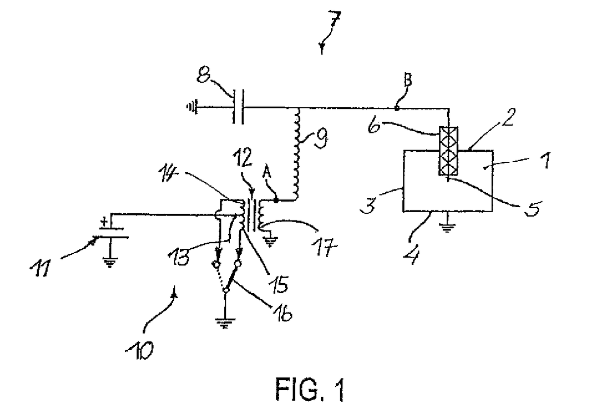
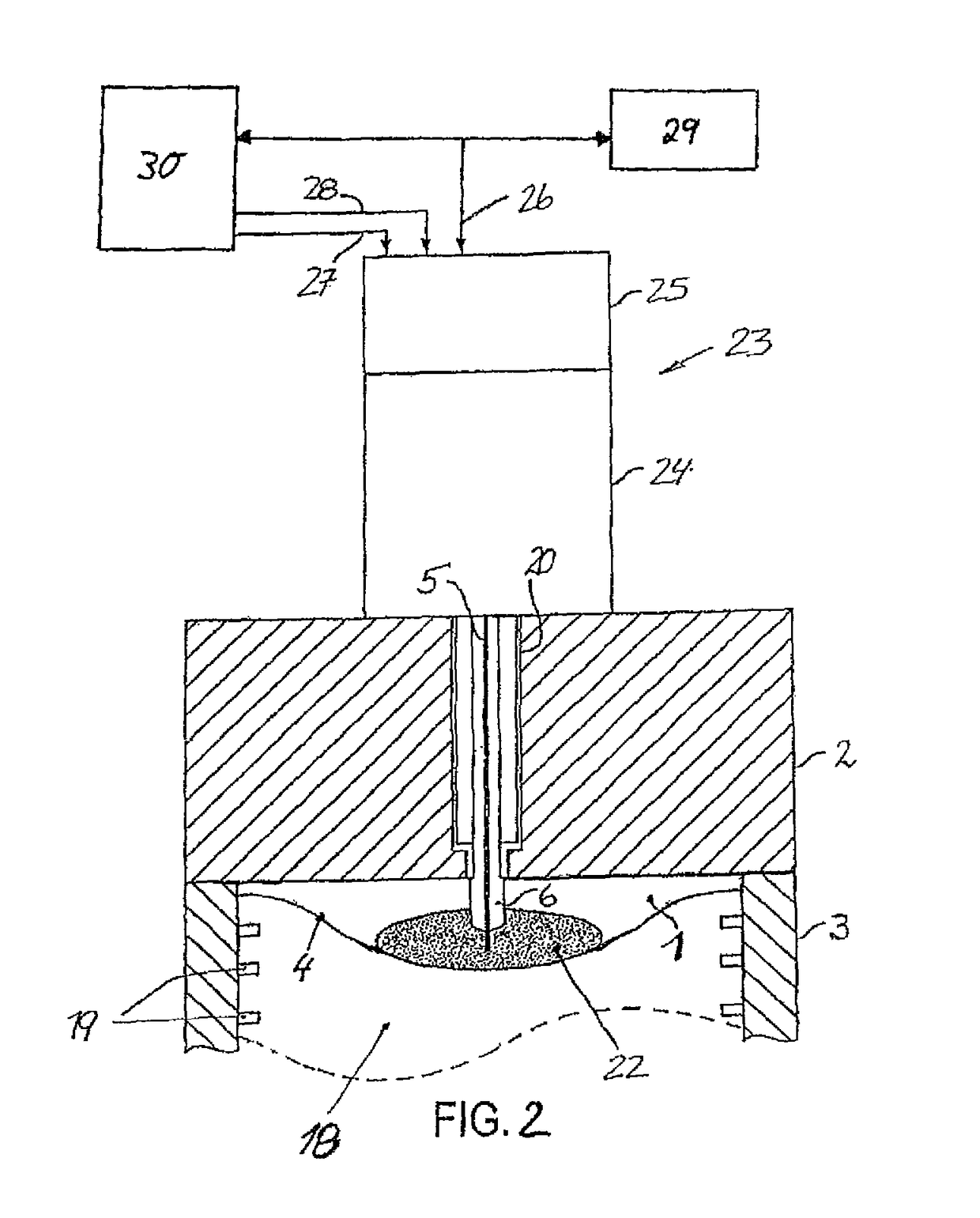
[0016]FIGS. 1 and 2 show a schematic depiction of an ignition system of the type disclosed in WO 2010 / 011838 A1. FIG. 1 shows a combustion chamber 1 which is delimited by walls 2, 3, and 4 that are at ground potential. An ignition electrode 5 which is enclosed by an insulator 6 along a portion of the length thereof extends into combustion chamber 1 from above, and is guided through upper wall 2 into combustion chamber 1 in an electrically insulated manner by way of said insulator. Ignition electrode 5 and walls 2 to 4 of combustion chamber 1 are part of a series oscillating circuit 7 which also includes a capacitor 8 and an inductance 9. Of course, series oscillating circuit 7 can also comprise further inductors and / or capacitors, and other components that are known to a person skilled in the art as possible components of series oscillating circuits.

[0017]A high-frequency generator 10 is provided for excitation of oscillating circuit 7, and comprises a DC voltage source 11 and a tra...


PUM


Abstract

Described is an igniter comprising an arrangement composed of an ignition electrode, an outer conductor coaxially enclosing the ignition electrode, and an electric insulator disposed between the ignition electrode and the outer conductor, via which insulator the ignition electrode and the outer conductor are interconnected, for igniting a fuel / air mixture in a combustion chamber, in particular in an internal combustion engine comprising one or more combustion chambers which are delimited by walls that are at ground potential, by creating a corona discharge in an area surrounding the tip of the ignition electrode. According to the invention, the ratio of the outer diameter d of the ignition electrode and the inner diameter D of the outer conductor is in the range of 0.3 to 0.44.

Description

BACKGROUND OF THE INVENTION[0001]Document WO 2004 / 063560 A1 discloses how a fuel / air mixture can be ignited in a combustion chamber of an internal combustion engine by a corona discharge created in the combustion chamber. For this purpose an ignition electrode is guided through one of the walls, that are at ground potential, of the combustion chamber in an electrically insulated manner and extends into the combustion chamber, preferably opposite a reciprocating piston provided in the combustion chamber. The ignition electrode constitutes a capacitance in cooperation with the walls of the combustion chamber that are at ground potential and function as counterelectrode. The combustion chamber and the contents thereof act as a dielectric. Air or a fuel / air mixture or exhaust gas is located therein, depending on which stroke the piston is engaged in.[0002]The capacitance is a component of an electric oscillating circuit which is excited using a high-frequency voltage which is created, f...

Claims


Application Information

Patent Timeline
Patent Type & Authority Patents(United States)
IPC IPC(8): F02P23/00F02P23/04
CPCH01T13/20
Inventor RUAN, GANGHUABRAEUCHLE, GERD
Owner BORGWARNER BERU SYST
Learn More