Portable ultrasound imaging system

a portable, ultrasound technology, applied in the field of portable ultrasound imaging systems, can solve the problems of large microchip area, inability to develop a simple variable-speed clock generator to date, and no prior art ultrasound imaging system utilizes the straightforward time-delay implementation. achieve the effect of improving system performance, less complex and expensive, and substantially reducing signal loss

Inactive Publication Date: 2013-06-25
TERATECH CORP
View PDF177 Cites 19 Cited by
  • Summary
  • Abstract
  • Description
  • Claims
  • Application Information

AI Technical Summary

Benefits of technology

[0024]In one embodiment, the portable processing circuitry is implemented in the form of a lap-top computer which can include an integrated keyboard, a PCMCIA standard modem card for transferring image data and a flip-top flat panel display, such as an active matrix LCD. The lap-top computer, and, therefore the entire system, can be powered by a small lightweight battery. The entire system, including scan head, cable and computer is therefore very lightweight and portable. The total weight of the system preferably does not exceed ten pounds. The interior of the scan head can also include a Faraday shield to shield the electronics of the scan head from interference from extraneous RF sources.
[0055]Another preferred embodiment of the invention incorporates the processing and control circuitry described herein in a distal end of an ultrasound internal probe or imaging catheter. This provides a more flexible and less expensive imaging probe that is useful for both diagnosis and treatment.

Problems solved by technology

There are two problems associated with these conventional techniques.
First, a simple variable-speed clock generator has not been developed to date.
Secondly, for an N-stage tapped delay line, the area associated with the tap select circuit is proportional to N2, thus such a circuit would require a large amount of microchip area to realize an integrated tap architecture.
Due to the difficulty and complexity associated with the generation of the control circuits of the conventional approach, only a few time-delay structures could be integrated on one microchip, and therefore a large number of chips would be needed to perform a multi-element dynamic beam forming function.
For these reasons, none of the prior art ultrasound imaging systems utilize the straightforward time-delay implementation.
Unfortunately, the mixer approximation method suffers from image misregistration errors as well as signal loss relative to the ideally-focused (perfect delay) case.
Modem ultrasound systems require extensive complex signal processing circuitry in order to function.
Even state-of-the-art CMOS chips only offer several hundred MOPS per chip, and each chip requires a few watts of electric power.
Thus, an ultrasound machine with a conventional implementation requires hundreds of chips and dissipates hundreds of watts of power.
Another drawback in conventional ultrasound systems is that the cable connecting the scan head to the processing and display unit is required to be extremely sophisticated and, hence, expensive.
Because the signals are of such a low level, they are extremely susceptible to noise, crosstalk and loss.
Such a cable requires expensive materials and extensive assembly time and is therefore very expensive.

Method used


Image

  • Portable ultrasound imaging system
  • Portable ultrasound imaging system
  • Portable ultrasound imaging system

Examples


Embodiment Construction

[0102]A description of preferred embodiments of the invention follows.

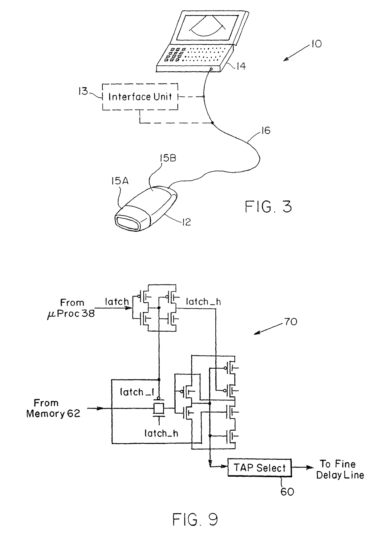
[0103]FIG. 3 is a schematic pictorial view of the ultrasound imaging system 10 of the present invention. The system includes a hand-held scan head 12 coupled to a portable data processing and display unit 14 which can be a lap-top computer. Alternatively, the data processing and display unit 14 can include a personal computer or other computer interfaced to a cathode ray tube (CRT) for providing display of ultrasound images. The data processor display unit 14 can also be a small, lightweight, single-piece unit small enough to be hand-held or worm or carried by the user. The hand-held display is less than 1000 cm3 in volume and preferably less than 500 cm3. Although FIG. 3 shows an external scan head, the scan head of the invention can also be an internal scan head adapted to be inserted through a lumen into the body for internal imaging. For example, the head can be a transesophogeal probe used for cardiac imaging...


PUM


Abstract

A portable ultrasound imaging system includes a scan head coupled by a cable to a portable battery-powered data processor and display unit. The scan head enclosure houses an array of ultrasonic transducers and the circuitry associated therewith, including pulse synchronizer circuitry used in the transmit mode for transmission of ultrasonic pulses and beam forming circuitry used in the receive mode to dynamically focus reflected ultrasonic signals returning from the region of interest being imaged.

Description

CROSS REFERENCE TO RELATED APPLICATIONS[0001]This application is a divisional of U.S. application Ser. No. 09 / 619,123 filed Jul. 19, 2000, now U.S. Pat. No. 7,500,952, which is a continuation-in-part of U.S. application Ser. No. 09 / 123,991 filed Jul. 28, 1998, now U.S. Pat. No. 6,106,472, which is a continuation of U.S. application Ser. No. 08 / 971,938 filed Nov. 17, 1997, now U.S. Pat. No. 5,957,846, which is a continuation of PCT / US96 / 11166 filed Jun. 28, 1996, now U.S. Pat. No. 5,964,709, which is a continuation-in-part of U.S. application Ser. No. 08 / 599,816 filed Feb. 12, 1996, now U.S. Pat. No. 5,690,114, which is a continuation-in-part of U.S. application No. 08 / 496,804 filed Jun. 29, 1995, now U.S. Pat. No. 5,590,658. The entire content of the above applications are being incorporated herein by reference.BACKGROUND OF THE INVENTION[0002]Typical conventional ultrasound systems can have transducer arrays which consist of 128 ultrasonic transducers. Each of the transducers is as...

Claims


Application Information

Patent Timeline
Patent Type & Authority Patents(United States)
IPC IPC(8): A61B8/14A61B7/04A61B8/00A61B8/12G01S7/00G01S7/52G01S15/89
CPCA61B8/56A61B8/463A61B8/546G01S7/003G01S7/52053G01S7/52063G01S7/52073G01S7/5208G01S15/8934G01S15/8979G01S15/8915A61B7/04A61B8/12A61B8/4455A61B8/4488A61B2560/045G01S7/52023G01S7/52025G01S7/52026G01S7/52046G01S15/899A61B8/00A61B8/4209A61B8/4236G01S7/52096
Inventor CHIANG, ALICEBROADSTONE, STEVEN R.
Owner TERATECH CORP
Why Eureka
Try Eureka