Heat pump comprising a cooling mode

a heat pump and cooling mode technology, applied in heat pumps, domestic cooling devices, lighting and heating devices, etc., can solve the problems of increasing entropy, constant losses, and reducing the effectiveness of the entire process, so as to eliminate primary heat exchanger losses, reduce the length of riser pipes, and reduce the effect of pressur

Active Publication Date: 2013-07-16
EFFICIENT ENERGY GMBH
View PDF12 Cites 5 Cited by
  • Summary
  • Abstract
  • Description
  • Claims
  • Application Information

AI Technical Summary

Benefits of technology

[0029]Thus, in accordance with the invention, the correct coolant is operated at the correct working pressures, water, in particular, vaporizing already at 22° C. in a negative-pressure atmosphere of 26 hPa, or at 100° C. at about 1.01 bar. By vaporizing, the water extracts the energy necessitated for this from the heat source. By employing a suitable heat sink, the steam will condense at a clearly reduced pressure, for example 10° C. at 12 hPa. In accordance with the invention, the transported heat energy is not simply introduced into the soil. Instead, by the vaporizing within the cooling evaporator, and the condensing within the cooling liquefier, both a high-pressure area on the side of the cooling evaporator and a low-pressure area on the side of the cooling liquefier are created, a balancing occurring between these two pressure areas via a generator, so that electrical energy is generated from the mechanical steam energy, which electrical energy may be fed into the power supply network, for example. What is further advantageous in the generation of the electrical energy is that the thermal energy given off into the heat sink is reduced as compared to an implementation where no electrical energy is generated. Thus, the heat sink is “spared”, since it only needs to absorb a minimum of heat.
[0049]In an embodiment, no heat exchanger is used even in the liquefier. Instead, the water vapor which is heated up due to being compressed is directly fed into the heating-system water within a liquefier, so that within the water, a liquefaction of the water vapor takes place such that even secondary heat-exchanger losses are eliminated.

Problems solved by technology

Pressure losses within valves, within the pressure and suction lines, of the compressor, etc. change the ideal curve of the cyclic process in the h, log p diagram and reduce the effectiveness of the entire process.
Then, when the piston again sucks in and compresses vapor, the temperature of the piston wall is initially fallen below again and then exceeded, which leads to constant losses.
What is also disadvantageous, in particular, is the heat exchange with the oil cycle of the piston compressor, which is indispensable for lubrication.
Any irreversible processes, such as heat losses during compression, pressure losses within the valves, and flow losses within the pressure line for liquefying and within the liquefier, will increase the entropy, i.e. the heat which cannot be retrieved.
Such an “overheating enthalpy” is undesired, in particular because the high temperatures occurring in the process will accelerate the aging of the compressor and, in particular, of the lubricating oil within a piston compressor.
Also, the effectiveness of the process is reduced.
These losses may be reduced if the liquid working material can dissipate its heat to a medium having a temperature smaller than T. This undercooling enthalpy may be exploited by an internal heat exchange which, however, also necessitates additional expenditure in terms of equipment.
Also in principle, the internal heat exchange has its limitation, because in the compression of the vapors, the overheating temperature T2 increases, whereby the gains achieved are partly cancelled out, and because also more thermal strain is put on the machine and the lubricating oil.
Eventually, the overheating causes the volume of the vapor to increase, whereby the volumetric heat power decreases.
Even though this working substance is no longer an “ozone killer”, there are nevertheless considerable requirements placed upon the completeness of the heat pump cycle, to the effect that no molecules of the working substance will escape from this closed cycle, since they would cause considerable damage due to the greenhouse effect.
This encapsulation leads to considerable additional cost when building a heat pump.
What is therefore disadvantageous about existing heat pumps, beside the fact of the harmful working substance, is also the fact that, due to the many losses within the heat pump cycle, the efficiency factor of the heat pump typically does not exceed a factor of 3.
When considering heat pumps wherein the compressor is driven by electrical current, and when considering, at the same time, that the efficiency factor in current generation is perhaps 40%, one will find that—with regard to the overall energy balance—the use of a heat pump is very questionable.
What is disadvantageous about this solution, however, is that a household will nevertheless necessitate a combustion engine and a fuel store even though it has no longer a classical heating system.
The expenditure made for engine and fuel storage has to be added to the expense made for the heat pump, which, after all, is a highly closed cycle due to the coolant being harmful to the climate.
All of these things have resulted in that heat pumps have had only limited success in competition with other types of heating systems.
Thus, in specific areas, a continuous period of warm weather often leads to the power supply network being overloaded, since many households start to switch on air conditioning systems in order to cool the building.
This results in electrical or mechanical energy and waste heat, but not in cooling.
This means that, particularly when cooling buildings, the risk of condensation within the building due to so-called “cold spots” will not occur, these cold spots otherwise being possible sources of mold formation, etc., in buildings not sufficiently aerated.
However, the electrical energy generated by the dynamic-type compressor which is operated as a generator by far exceeds the energy that has to be employed for the heating circulating pump.

Method used


Image

  • Heat pump comprising a cooling mode
  • Heat pump comprising a cooling mode
  • Heat pump comprising a cooling mode

Examples


Embodiment Construction

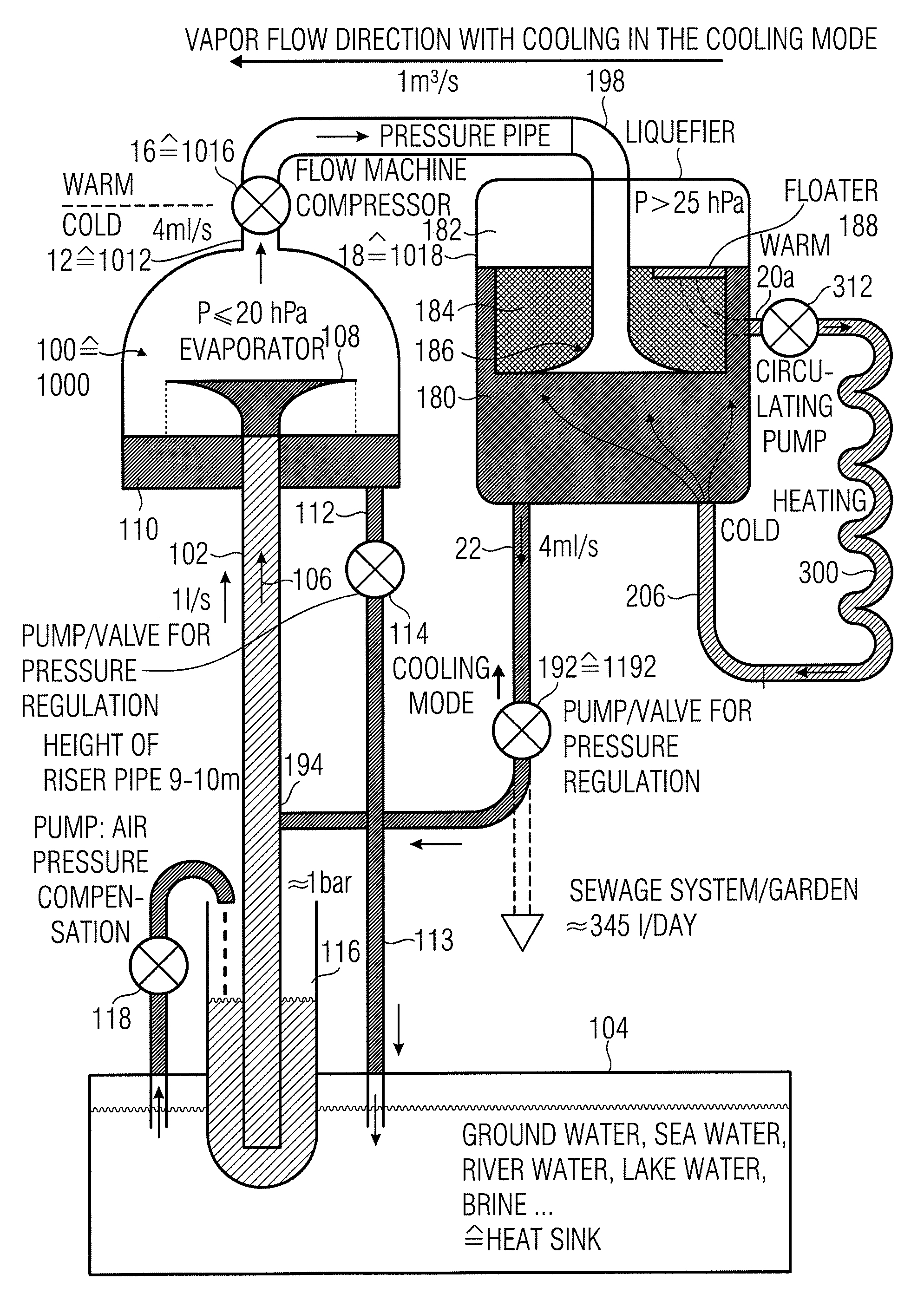
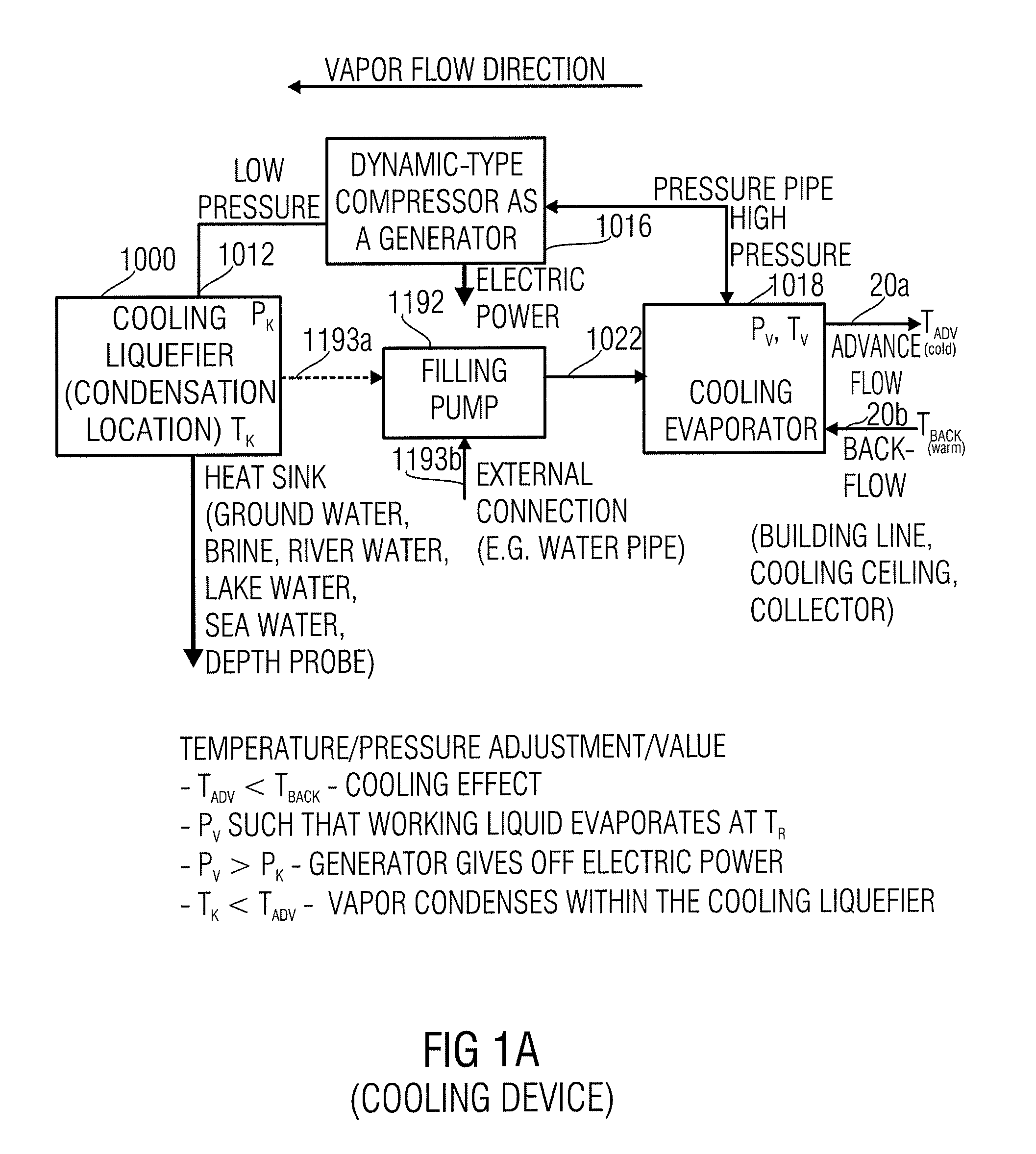
[0072]FIG. 1A shows an inventive fundamental representation of the heat pump comprising a cooling mode, or of the cooling method, the cooling method immediately resulting from the functionalities of the heat pump comprising a cooling mode. The inventive heat pump comprising a cooling mode includes a cooling evaporator 1018 having a comparatively high pressure PV. In particular, the cooling evaporator 1018 further comprises a heating advance flow 20a having an advance flow temperature TADV, and a heating backflow 20b having a backflow temperature TBACK. In particular, the cooling evaporator may be brought to such a pressure PV that a vaporization temperature is below a temperature of an object to be cooled with which the heating backflow 20b may be thermally coupled. The backflow temperature TBACK is thus higher than the advance flow temperature TADV, which is why the heating advance flow 20a is referred to as “cold”, whereas the heating backflow 20b is referred to as “warm”. The coo...


PUM


Abstract

A heat pump having a cooling mode includes a cooling evaporator coupled to an advance flow and a backflow. The cooling evaporator is brought to a pressure such that a vaporization temperature of the working liquid in the backflow is below a temperature of an object to be cooled to which the backflow may be thermally coupled. In this manner, an area having vapor at high pressure is generated. This vapor is fed into a dynamic-type compressor which outputs the vapor at a low pressure and provides electrical energy in the process. The vapor at low pressure is fed to a cooling liquefier which provides vapor liquefaction at a low temperature, this temperature being lower than the temperature of the object to be cooled. The working liquid removed from the cooling evaporator due to the vaporization is refilled by a filling pump. The heat pump having a cooling mode also results when a specific heat pump is operated in the reverse direction, and provides cooling without any net use of electrical energy. Instead, the cooling even generates electrical energy.

Description

CROSS-REFERENCE TO RELATED APPLICATIONS[0001]This application is a U.S. national entry of PCT Patent Application Serial No. PCT / EP2007 / 010197 filed 23 Nov. 2007, and claims priority to German Patent Application No. 102006056798.6 filed on 1 Dec. 2006, which is incorporated herein by reference in its entirety.BACKGROUND OF THE INVENTION[0002]The present invention relates to heat pumps, and in particular to heat pumps comprising a cooling mode.[0003]FIG. 8 shows a known heat pump as is described in “Technische Thermodynamik”, Theoretische Grundlagen and praktische Anwendungen, 14th revised edition, Hanser Verlag, 2005, pp. 278-279. The heat pump includes a closed cycle, within which a working substance, such as R 134a, circulates. Via a first heat exchanger 80 and the evaporator, so much heat is withdrawn from the soil, or the ground water, that the working substance evaporates. The working substance, which now is rich in energy, is extracted by the compressor via the suction line. Wi...

Claims


Application Information

Patent Timeline
Patent Type & Authority Patents(United States)
IPC IPC(8): F25B13/00
CPCF25B19/00F25B30/06Y02B30/52
Inventor SEDLAK, HOLGERKNIFFLER, OLIVER
Owner EFFICIENT ENERGY GMBH
Why Eureka
Try Eureka