
Protective device

a protection device and shielding technology, applied in the direction of waveguide devices, emergency protective arrangements for limiting excess voltage/current, coupling device connections, etc., can solve the problems of reducing the effectiveness of protection devices, reducing the efficiency of protection devices, and reducing the likelihood of significant damage to any sensitive components connected, so as to achieve easy assembly, low cost, and the effect of reducing the risk of damag

Active Publication Date: 2013-07-16
KAUFFMAN GEORGE M
View PDF3 Cites 16 Cited by
  • Summary
  • Abstract
  • Description
  • Claims
  • Application Information

AI Technical Summary

Benefits of technology

The present invention provides a device that is small, consists of a limited number of parts, easy to assemble, and inexpensive to manufacture. Additionally, this device can be reused multiple times without losing its effectiveness.

Problems solved by technology

It has been found that, on occasion, potentially harmful voltages are transmitted through RF transmission lines.
As a result, it has been found that radio antennae are highly susceptible to lightening strikes, the high electrical energy of a lightning strike increasing the likelihood of significant damage to any sensitive components connected to the transmission line, which is highly undesirable.
The operational frequency of protective devices which utilize shunt conductors is typically greater than 400 MHz because lower frequencies require excessively long shunt conductors.
As can be appreciated, the use of excessively long shunt conductors is disfavored, among other reasons, for substantially increasing the overall size of the protective device.
Although well known in the art, coaxial electric devices of the type as described above typically suffer from at least some of following shortcomings.
As can be appreciated, it has been found that the utilization of a center conductor of the type as described in detail above significantly increases manufacturing costs.
In particular, in order to provide each pin of the inner conductor with its associated threading, a complex machining process is required.
Furthermore, the process of assembling the various pieces of the center conductor together and, in turn, to the shunt conductor necessitates a considerable labor requirement, thereby significantly increasing manufacturing costs, which is highly undesirable.
As a second drawback, coaxial electric devices of the type as described above include an outer conductor that is typically constructed entirely out of a highly conductive, hardened metallic material, such as brass, copper or the like, for performance purposes.
However, as can be appreciated, the aforementioned materials that are traditionally used to form the outer conductor a coaxial electric device are relatively expensive in nature, which is highly undesirable.
Furthermore, it is to be understood that if the outer conductor of a protective device were manufactured using a softer, less expensive conductive material, such as aluminum, the performance of the device may be compromised.
Specifically, the inherent softness of alternative metals will ultimately result in their deformation in the region of contact during the coupling process.
Accordingly, over time, this deformation of the material in its region of contact may result in insufficient conductive coupling, which is highly undesirable.
As a third drawback, in order to provide a conventional coaxial electric device of the type described in detail above with wideband capabilities, substantial modification of the configuration of the inner and / or outer conductor is typically required, which is highly undesirable in certain applications.
In addition, it has been found that modifying the configuration of either the inner conductor or the outer conductor can in turn compromise the radio frequency (RF) performance of the device.

Method used


Image

  • Protective device
  • Protective device
  • Protective device

Examples


Embodiment Construction

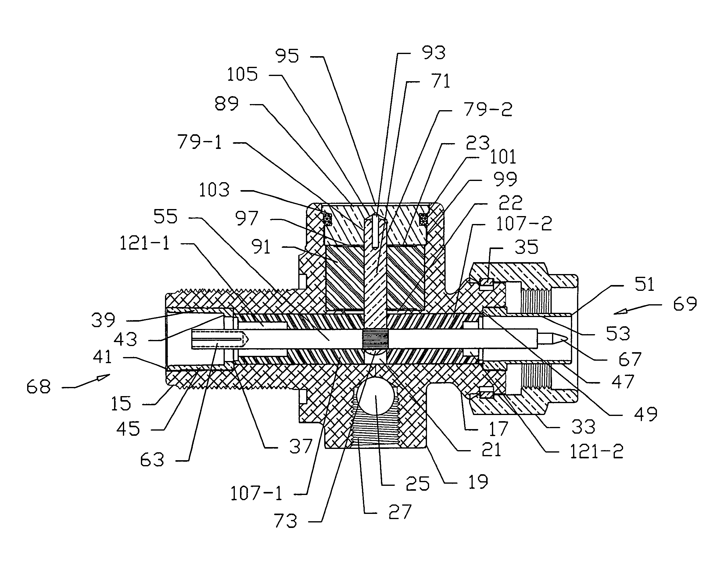
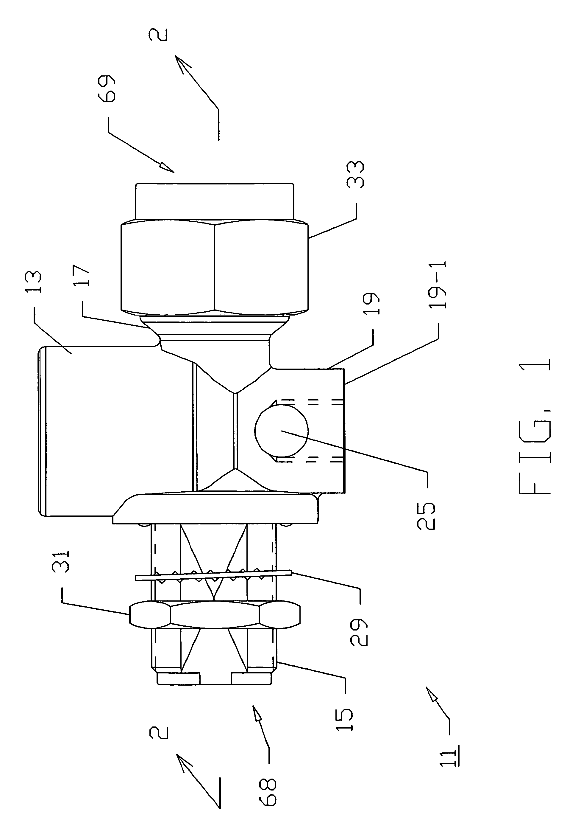
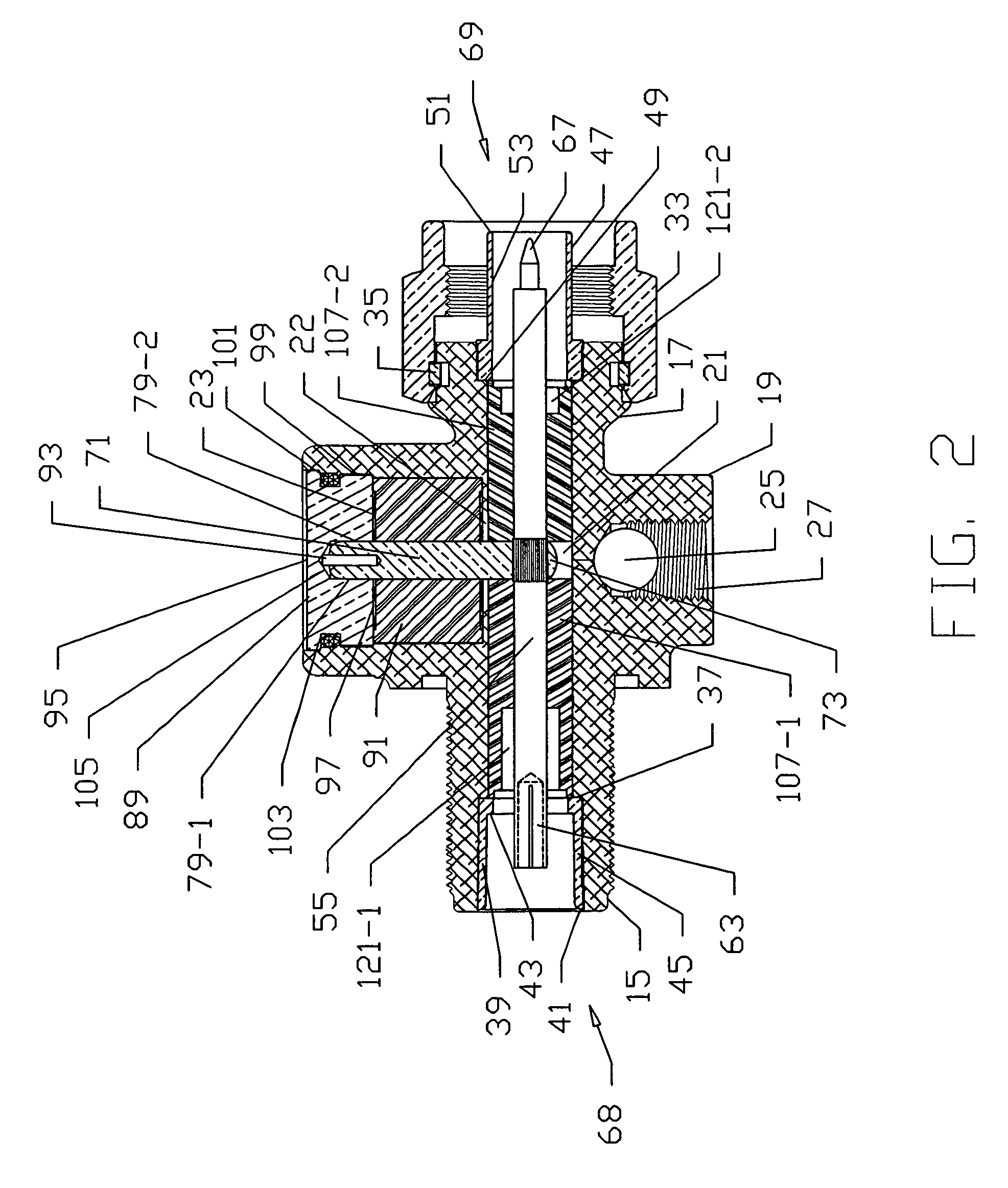
[0033]Referring now to FIGS. 1 and 2, there is shown a protective device for a radio frequency (RF) transmission line that is designed to transmit electromagnetic signals of a desired frequency band between a source and a load, the protective device being constructed according to the teachings of the present invention and represented generally by reference numeral 11. As will be described further below, protective device provides over-voltage protection to the transmission line, thereby precluding potentially harmful transient voltages from being transmitted to the load.

[0034]Protective device 11 comprises an outer conductor 13 that serves as the return path, or ground, for the communication signal. Preferably, outer conductor 13 is cast, forged or otherwise constructed from a single conductive material that is relatively inexpensive in nature, such as aluminum, zinc, aluminum-based alloys or zinc-based alloys. As will be described further in detail below, protective device 11 is sp...


PUM


Abstract

A device for protecting a radio frequency transmission line from transient voltages includes an inner conductor for transmitting communication signals of a desired frequency band and a grounded, coaxial outer conductor electrically insulated from the inner conductor by a pair of annular insulators. As one feature of the invention, a tap conductor for discharging transient voltages carried by the inner conductor that fall outside the desired frequency band is coupled at one end to the inner conductor through a press-fit connection. As another feature of the invention, a pair of high-quality contacts are mounted onto opposite ends of the outer conductor and serve, together with the inner conductor, as the only electrical contact surfaces for the protective device that transmit the desired communication signals. As another feature of the invention, each insulator has a constant outer diameter along the entirety of its length and a variable inner diameter.

Description

CROSS-REFERENCE TO RELATED APPLICATIONS[0001]The present application claims the benefit of U.S. Provisional Patent Application Ser. No. 61 / 127,450, which was filed on May 13, 2008 in the name of George M. Kauffman, and is a continuation-in-part of presently-pending U.S. patent application Ser. No. 12 / 072,818, filed on Feb. 28, 2008 in the name of George M. Kauffman, which is in turn a continuation of U.S. patent application Ser. No. 10 / 727,076, filed on Dec. 2, 2003, in the name of George M. Kauffman, now U.S. Pat. No. 7,440,253, which issued on Oct. 21, 2008, which in turn is a continuation-in-part of PCT Application Number PCT / US02 / 18919 filed Jun. 14, 2002 in the name of George M. Kauffman, which in turn claims the benefit of U.S. Provisional Patent Application Ser. No. 60 / 298,439, which was filed on Jun. 15, 2001 in the name of George M. Kauffman, all of said disclosures being incorporated herein by reference.BACKGROUND OF THE INVENTION[0002]The present invention relates general...

Claims


Application Information

Patent Timeline
Patent Type & Authority Patents(United States)
IPC IPC(8): H01C7/12H02H9/06H02H1/00H02H1/04H02H3/22
CPCH01P1/045H01P1/202H01R24/44H01R13/6625H01R13/719H01R24/48H01R2103/00
Inventor KAUFFMAN, GEORGE M.
Owner KAUFFMAN GEORGE M
Learn More