Light emitting system according to a polariton mode with electrical injection of quantum wells

a light-emitting system and quantum well technology, applied in the field of semiconductor light sources, can solve the problems of loss of energy, impossibility of obtaining the laser effect, and great difficulty

a light-emitting system and quantum well technology, applied in the field of semiconductor light sources, can solve the problems of loss of energy, impossibility of obtaining the laser effect, and great difficulty

US8498318B2Active Publication Date: 2013-07-30CENT NAT DE LA RECHERCHE SCI

Image

  • Light emitting system according to a polariton mode with electrical injection of quantum wells
  • Light emitting system according to a polariton mode with electrical injection of quantum wells
  • Light emitting system according to a polariton mode with electrical injection of quantum wells

Examples


Embodiment Construction

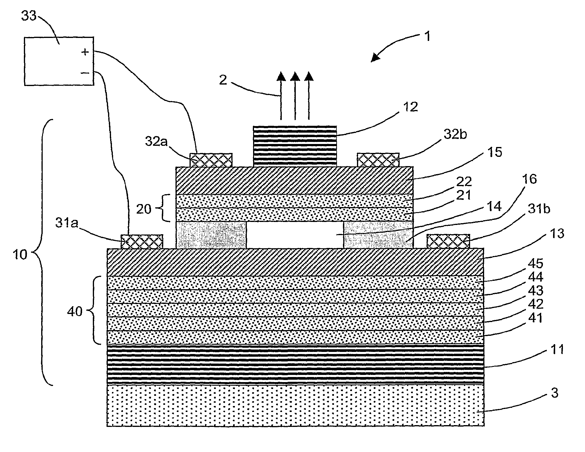
[0047]As shown in FIG. 1, the system 1 for emitting light 2 according to a particular embodiment of the invention comprises a substrate 3 and an optical cavity 10. It is designed to operate in a specific emission wavelength.

[0048]In this embodiment, the system comprises two electrically injected quantum wells 21 and 22 and five non-injected quantum wells 41 to 45. This choice of the number of wells is imposed by the necessity for clarity in the figure. As such, those skilled in the art will be able to choose a more suitable number of quantum wells. In particular, a number of injected wells less than 5 can be chosen and a number of non-injected wells that is clearly higher which could be of a magnitude of 60 for a structure having GaN quantum wells. Those skilled in the art will note indeed that a large total number of quantum wells favors the polariton laser effect.

[0049]This system can be obtained according to an epitaxy technique via molecular beam on the substrate 3, which is a t...


PUM


Abstract

A light (2) emitting system (1) includes an optical cavity (10) having at least one optical mode and including at least one transmissive reflector (12), a first set (20) of quantum wells (21, 22) and elements (31, 32, 33) of electrical injection of the quantum wells of the first set. The quantum wells of the first set are arranged so that at least one of their electronic resonances is a strong coupling regime with an optical mode of the optical cavity and emits a light according to a mixed exciton-polariton mode. The optical cavity further includes a second set (40) of quantum wells (41, 42, 43, 44, 45) arranged outside of the direct range of the elements of electrical injection and arranged in relation to the quantum wells of the first set so that at least one of their electronic resonances is in a strong coupling regime with the mixed exciton-polariton mode of the optical cavity.

Description

[0001]This invention relates to a light emitting system according to a polariton mode with electrical injection of quantum wells.TECHNICAL FIELD[0002]This invention relates to the field of semiconductor light sources using quantum well structures for the purposes of obtaining an effect of the “polariton laser” type.[0003]It relates more particularly to a light emitting system comprising an optical cavity having at least one optical mode and comprising at least one transmissive reflector, a first set of quantum wells and means of electrical injection of these quantum wells of the first set. The quantum wells of the first set are arranged in such a way that at least one of their electronic resonances is a strong coupling regime with an optical mode of said optical cavity and emits a light according to a mixed exciton-polariton mode.PRIOR ART[0004]Semiconductor lasers are used to produce monochromatic and intense light beams. They are pumped using an electric current circulating in a P...

Claims


Application Information

Patent Timeline
30 Jul 2013
Publication
US8498318B2
IPC
H01S5/00
CPC
B82Y20/00; H01S5/042; H01S5/34333; H01S5/18308; H01S5/10; H01S5/18369; H01S5/18383
Inventors
MALPUECH, GUILLAUME; SOLNYSHKOV, DMITRY