Vehicle parking brake and operating method

Active Publication Date: 2013-08-06
ZF CV SYST EURO BV
View PDF12 Cites 2 Cited by
  • Summary
  • Abstract
  • Description
  • Claims
  • Application Information

AI Technical Summary

Benefits of technology

[0008]Generally speaking, it is an object of the present invention to provide a co

Problems solved by technology

Furthermore, for vehicles equipped with wheel speed sensors, braking with anti-lock protection is still possible by means of the parking brake even if the signal

Method used


Image

  • Vehicle parking brake and operating method
  • Vehicle parking brake and operating method
  • Vehicle parking brake and operating method

Examples


Embodiment Construction

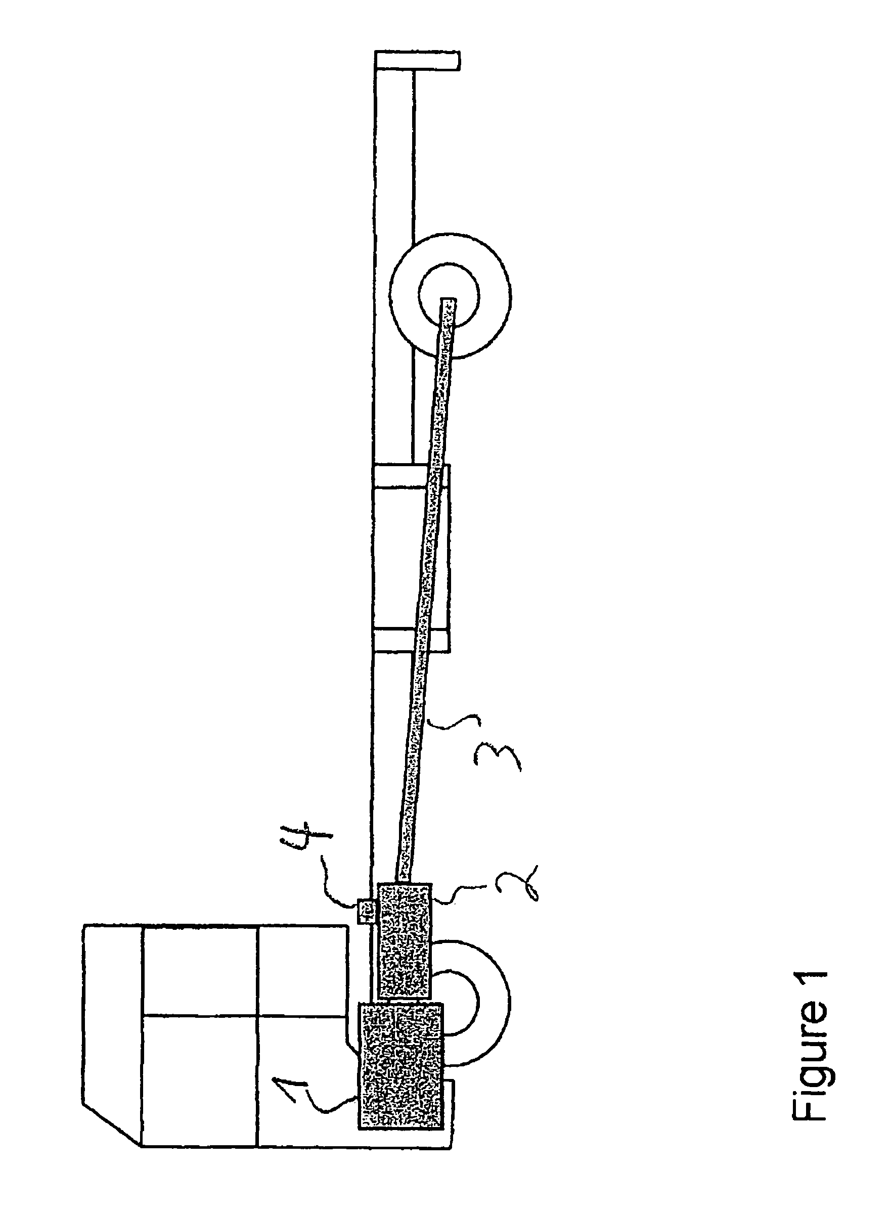
[0028]Referring now to the drawing figures, FIG. 1 is a schematic illustration of a vehicle that has an engine 1, a transmission 2 and a drive shaft 3 for driving the vehicle. In addition, a rotational speed sensor 4 is shown that senses the output speed of the transmission. On the basis of the signal of the rotational speed sensor 4, a TCO signal is calculated in a control unit (not illustrated in FIG. 1) such as, for example, an engine control unit or transmission control unit.

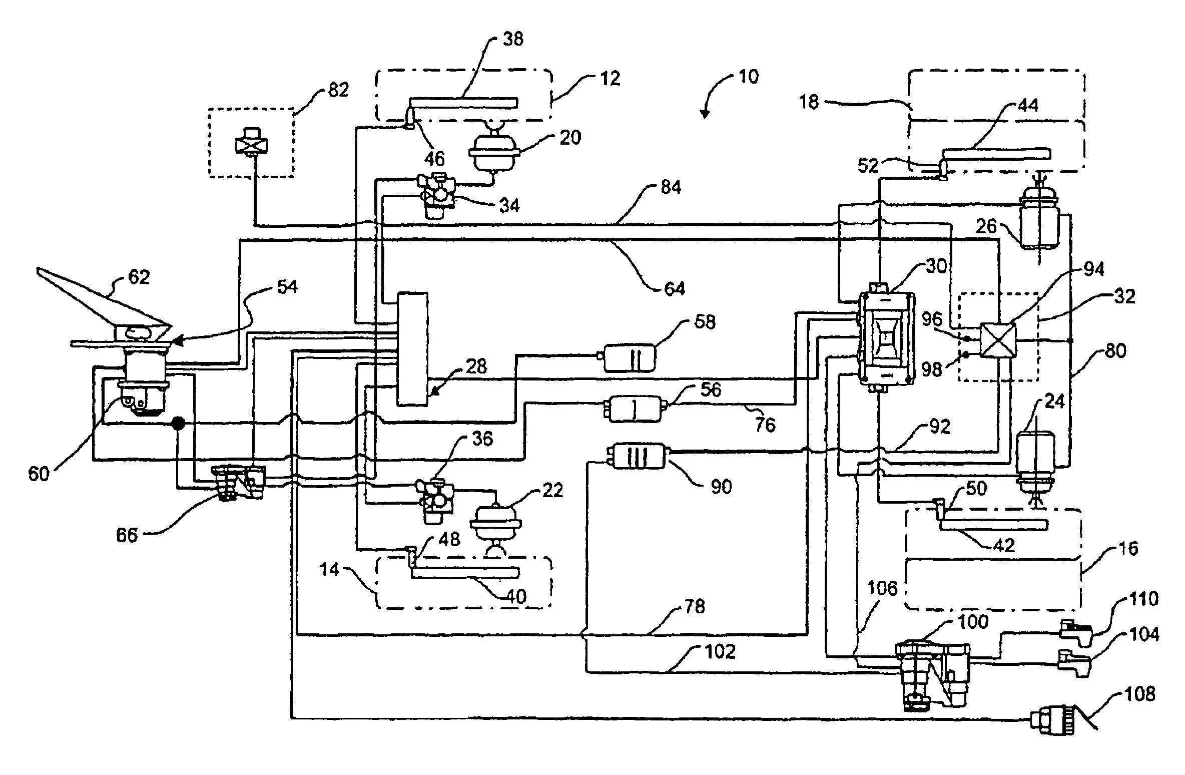
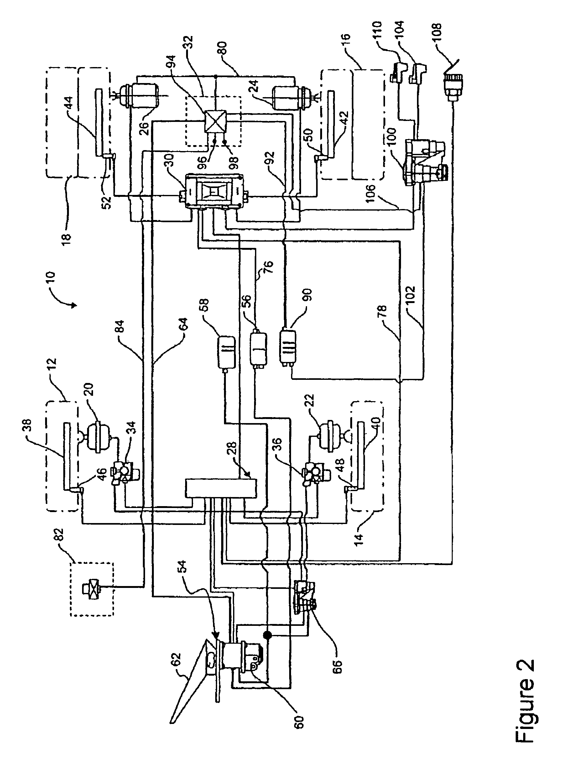
[0029]FIG. 2 is a schematic illustration of a compressed air brake system 10 for a vehicle having four wheels 12, 14, 16, 18. The brake system 10 is controlled electrically, i.e., the metering of brake pressure to brake cylinders 20, 22, 24, 26 of the wheels 12, 14, 16, 18 is controlled by electrical and electronic control elements. The brake cylinders 20, 22 of the front wheels 12, 14 are controlled by a front-axle brake control module 28, and the brake cylinders 24, 26 of the rear wheels 16, 18 are control...


PUM


Abstract

A parking brake of a brake system for a vehicle includes an anti-lock device, which, based on a signal that is dependent on the rotational speed of the vehicle engine, transmission, or drive shaft, prevents blocking or excess slippage of a wheel that can be decelerated by the parking brake.

Description

FIELD OF THE INVENTION[0001]The present invention generally relates to a parking brake of a vehicle brake system.BACKGROUND OF THE INVENTION[0002]Brake systems comprise not only a service brake but usually also a parking brake in order to be able to shut down the vehicle with the brake engaged. Such a parking brake is also referred to as a handbrake.[0003]Parking brakes for brake systems that are operated by pressurized media generally have spring-loaded brake cylinders in which a storage spring engages the brake so that the vehicle is braked or can no longer be moved. This parking brake is released by applying compressed air to a spring store part of a spring-loaded brake cylinder, so that the storage spring is compressed and the parking brake is therefore released.[0004]The supply of compressed air to the spring store part in order to release the parking brake is provided by means of an air-quantity-boosting valve device, in particular a relay valve. The air-quantity-boosting valv...

Claims


Application Information

Patent Timeline
IPC IPC(8): B60T8/32
CPCB60T8/1708B60T13/385B60T13/662B60T17/18
Inventor BENSCH, UWEDJIYA, GUY ALAIN DJEUTCHOUANGFORSTER, HENNINGROSENDAHL, HARTMUTSTRACHE, WOLFGANGSTRUWE, OTMAR
Owner ZF CV SYST EURO BV
Why Eureka
Try Eureka