
Supercapacitor cells and micro-supercapacitors

a supercapacitor and micro-supercapacitor technology, applied in the direction of electrical apparatus casings/cabinets/drawers, electrical apparatus casings/cabinets/drawers, etc., can solve the problems of short charging time, high cycling stability, and long shelf life of supercapacitors

Inactive Publication Date: 2013-08-06
HRL LAB
View PDF9 Cites 50 Cited by
  • Summary
  • Abstract
  • Description
  • Claims
  • Application Information

AI Technical Summary

Benefits of technology

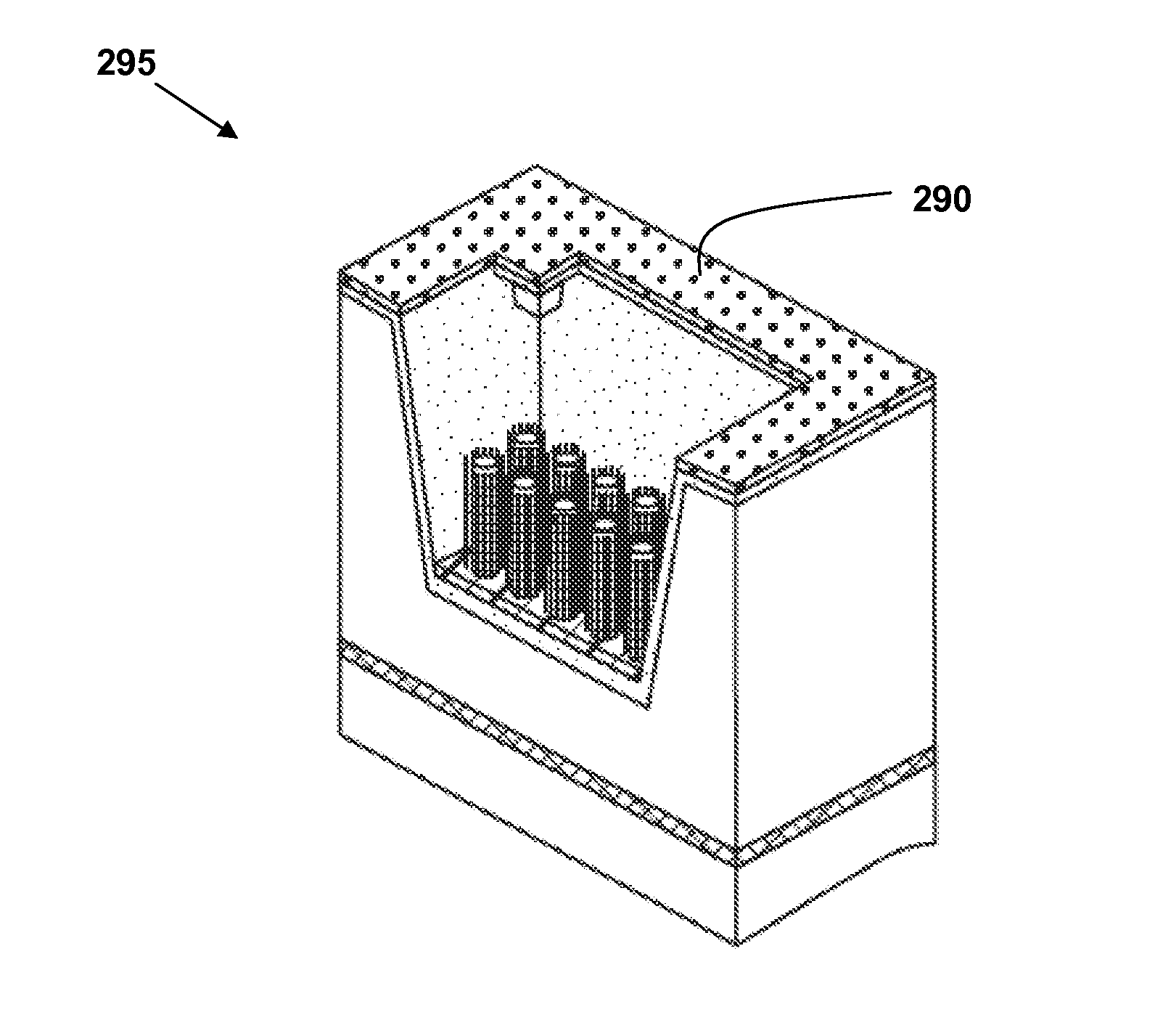
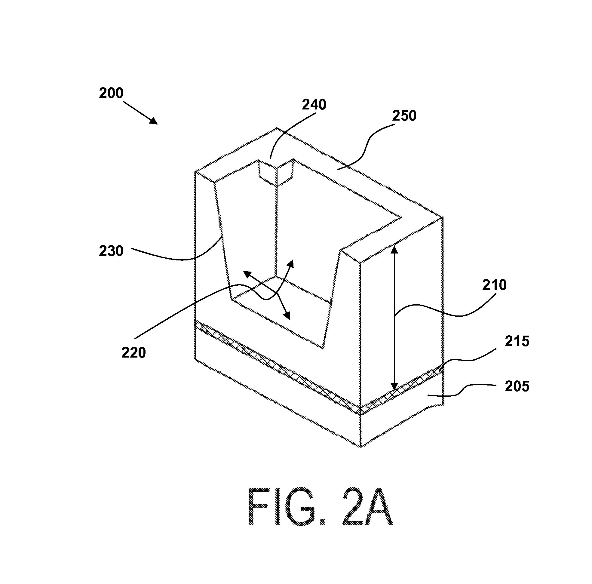
The present invention provides a method for fabricating a supercapacitor by etching a cavity in a silicon-on-insulator wafer and depositing electrodes and a catalyst layer to promote growth of carbon nanostructures. The carbon nanostructures are then coated with metal oxide and an electrolyte is introduced into the cavity. The resulting supercapacitor includes a hermetic seal between the cavity and the lid, and first and second carbon nanostructures that are electrically continuous with the electrodes. The method allows for the growth of carbon nanostructures in the cavity and on the electrodes, resulting in a high surface area for energy storage. The supercapacitor does not require a cell separator and includes a lid and cavity that are both silicon. The carbon nanostructures can be connected to catalyst layers comprising iron, nickel, cobalt, or yttrium. The technical effects of the invention include a high surface area for energy storage, improved energy density, and a simplified method for fabricating a supercapacitor.

Problems solved by technology

In particular, supercapacitors have great potential for applications that require a combination of high power, short charging time, high cycling stability, and long shelf life.
Despite greater capacitances than conventional capacitors, supercapacitors have yet to match the energy densities of many batteries and fuel cells.
That is, a battery can store more total energy than a capacitor, but it cannot deliver it very quickly—which means its power density is low.
Typical micro-supercapacitors employ cell separators which take up valuable cavity space in a sub-100 μm size device, and thus reduce the energy capacity of the supercapacitor.

Method used


Image

  • Supercapacitor cells and micro-supercapacitors
  • Supercapacitor cells and micro-supercapacitors
  • Supercapacitor cells and micro-supercapacitors

Examples


Embodiment Construction

[0077]The apparatus, devices, systems, and methods of the present invention will now be described in detail by reference to various non-limiting embodiments, including the figures which are exemplary only.

[0078]Unless otherwise indicated, all numbers expressing dimensions, capacities, and so forth used in the specification and claims are to be understood as being modified in all instances by the term “about.” Without limiting the application of the doctrine of equivalents to the scope of the claims, each numerical parameter should at least be construed in light of the number of reported significant digits and by applying ordinary rounding techniques.

[0079]As used in this specification and the appended claims, the singular forms “a,”“an,” and “the” include plural referents unless the context clearly indicates otherwise.

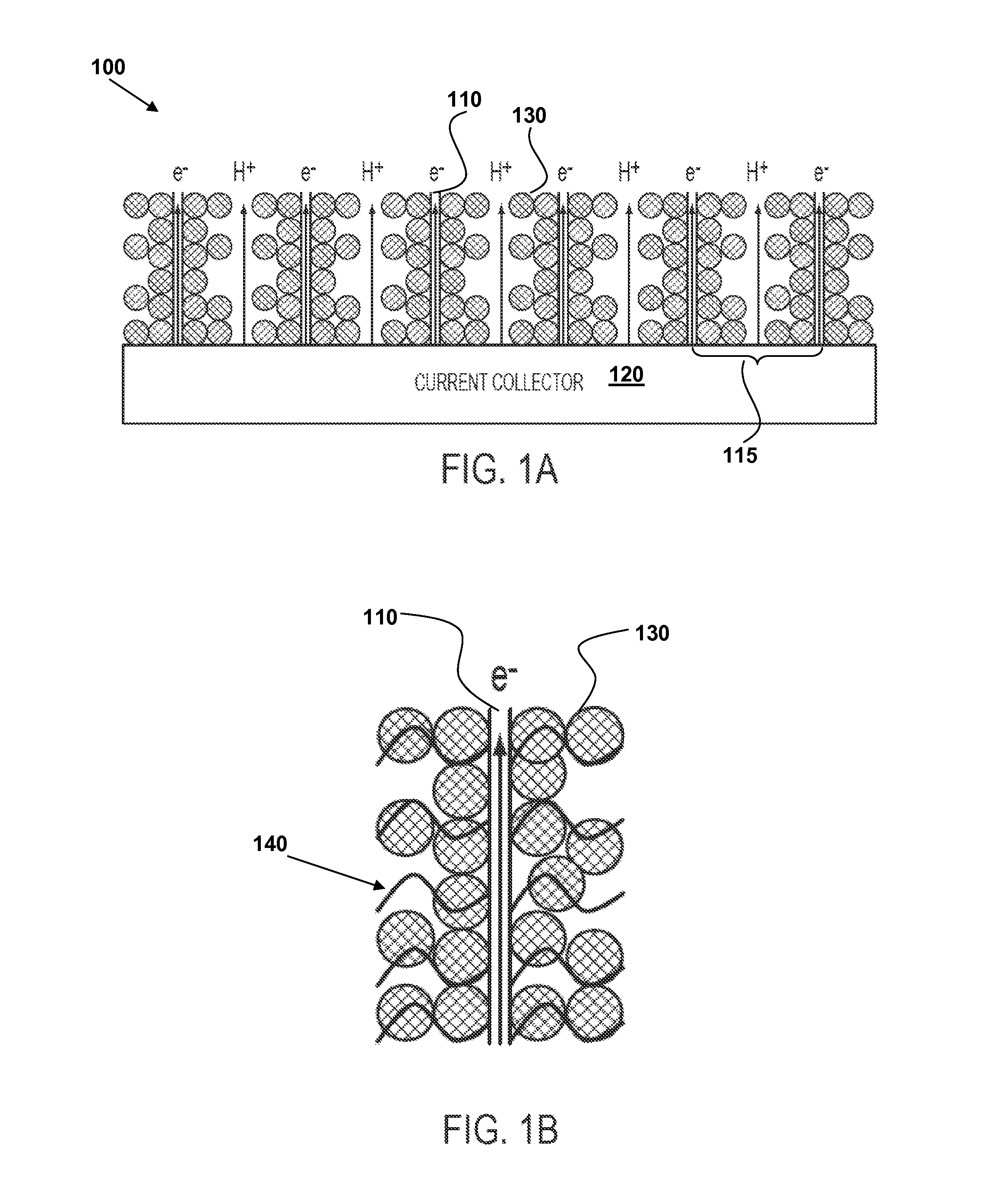
[0080]Some variations of the invention utilize a composite structure 100 for good energy and power density in a supercapacitor, as depicted in FIG. 1A. In these variat...


PUM

PropertyMeasurementUnit
lengthaaaaaaaaaa
temperatureaaaaaaaaaa
outer diametersaaaaaaaaaa

Abstract

This invention provides a micro-supercapacitor with high energy density and high power density. In some variations, carbon nanostructures, such as carbon nanotubes, coated with a metal oxide, such as ruthenium oxide, are grown in a supercapacitor cavity that contains no separator. A lid is bonded to the cavity using a bonding process to form a hermetic seal. These micro-supercapacitors may be fabricated from silicon-on-insulator wafers according to the disclosed methods. An exemplary micro-supercapacitor is cubic with a length of about 50-100 μm. The absence of a separator translates to higher energy storage volume and less wasted space within the supercapacitor cell. The energy density of the micro-supercapacitor may exceed 150 J / cm3 and the peak output power density may be in the range of about 2-20 W / cm3, in various embodiments.

Description

STATEMENT REGARDING FEDERALLY SPONSORED RESEARCH OR DEVELOPMENT[0001]This invention was made with Government support under Contract No. FA8650-06-C-7621. The Government has certain rights in this invention.FIELD OF THE INVENTION[0002]The present invention generally relates to supercapacitors and energy-storage and energy-delivery devices that include supercapacitor structures.BACKGROUND OF THE INVENTION[0003]Energy has become a primary focus throughout the world. There has been great interest in developing more efficient energy-storage devices. A supercapacitor is a type of energy-storage device with a broad spectrum of potential uses. In particular, supercapacitors have great potential for applications that require a combination of high power, short charging time, high cycling stability, and long shelf life.[0004]Supercapacitors, also known as ultracapacitors or electrochemical capacitors, generally can achieve capacitances several orders of magnitude larger than conventional capac...

Claims


Application Information

Patent Timeline
Patent Type & Authority Patents(United States)
IPC IPC(8): H01G9/00H01G9/08
CPCH01G9/00H01L29/0676H01G11/10H01G11/28H01G11/36H01G11/46H01G11/82B82Y10/00B82Y40/00H01L28/91H01G9/08Y02E60/13H01L29/66439H01L29/66469H01L29/775H01L29/92H01L29/20
Inventor CHANG, DAVID T.PATTERSON, PAMELA R.LIU, PING
Owner HRL LAB
Learn More