Inspection system with fiber coupled OCT focusing

Active Publication Date: 2013-08-13
KLA TENCOR TECH CORP
View PDF11 Cites 10 Cited by
  • Summary
  • Abstract
  • Description
  • Claims
  • Application Information

AI Technical Summary

Benefits of technology

[0032]Since the beam splitter 118 does not require a pzt stage, a Z degree of freedom can be added to the stage that holds the sample and shifting elements can be avoided in the imaging channel. The above mentioned improvements in the imaging system are expected to improve robustness, mechanical tolerances and optical performance.
[0033]Another advantage for using the large bandwidth OCT system is the straightforward incorporation of such a system in a thin film inspection or metrology tool.
[0034]In the focusing phase of the metrology process, broadband illumination can flood the OCT and optical system. A sample stage 126 to which the sample 124 is mounted can be scanned in a Z direction causing detection of a narrow interferometric signal which in turn can be used to determine an optimal focus position. After focusing, the reference mirror 204 is scanned so that interferometric sectioning information about the sample 124 can be collected and analyzed. The robust optical system and environmentally controlled interferometer proposed here supports the achievement of sectioning information with high precision

Problems solved by technology

First, in a Linnik-type configuration the reference objective 120 has similar optical performance to the main objective 122 and is, therefore, expensive.
The mechanical shutter 109 is often a source of noise that can cause vibration.
This adds to the complexity and expense of the tool 100.
Furthermore, because the focusing system uses the same illumination as is used for metrology, the spectrum available for focusing is constrained to the bandwidth used

Method used


Image

  • Inspection system with fiber coupled OCT focusing
  • Inspection system with fiber coupled OCT focusing
  • Inspection system with fiber coupled OCT focusing

Examples


Embodiment Construction

[0019]Although the following detailed description contains many specific details for the purposes of illustration, anyone of ordinary skill in the art will appreciate that many variations and alterations to the following details are within the scope of the invention. Accordingly, the examples of embodiments of the invention described below are set forth without any loss of generality to, and without imposing limitations upon, the claimed invention.

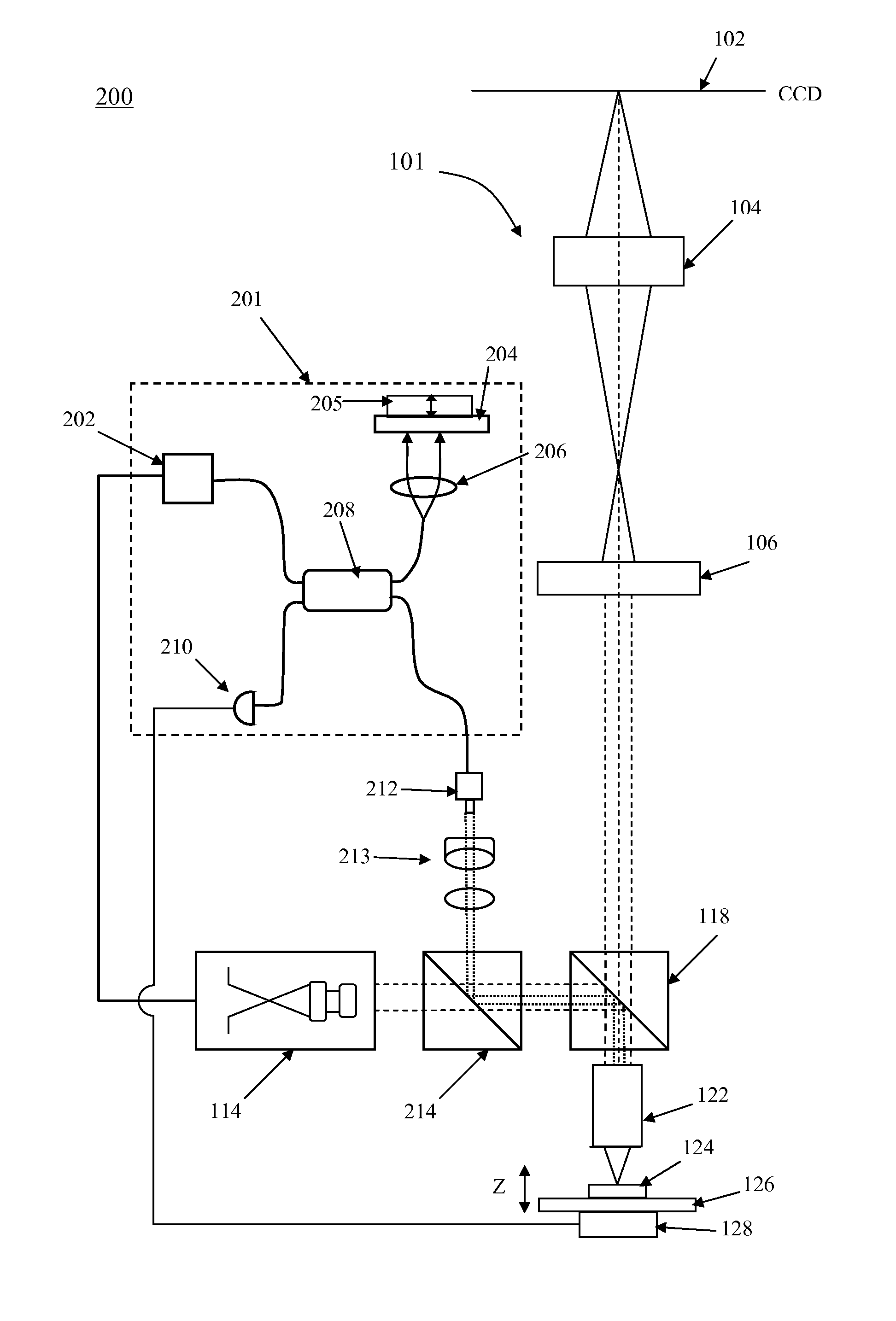
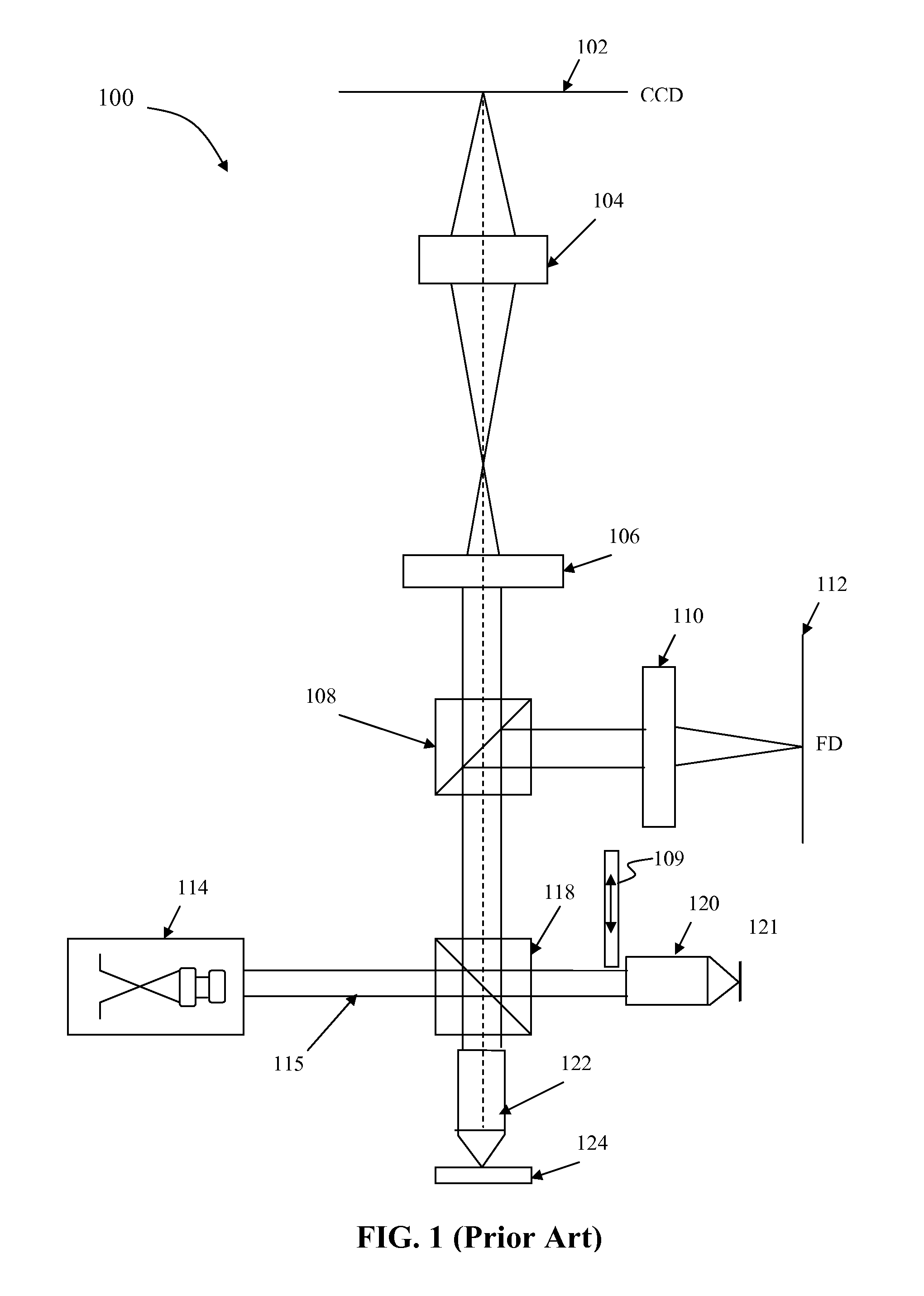
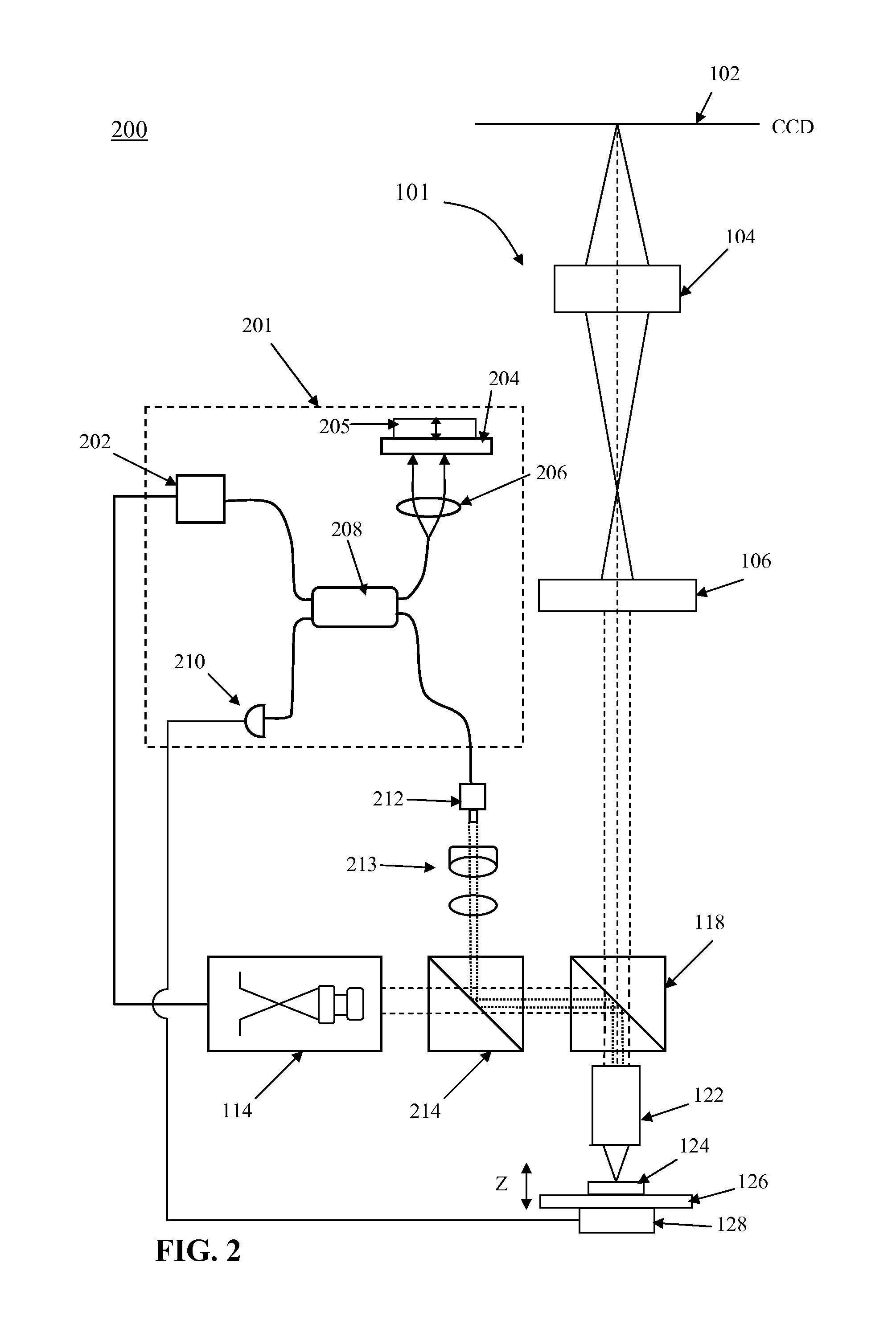
[0020]Embodiments of the present invention are directed to inspection systems that incorporate an OCT focus system in a configuration with the potential for reduced cost and improved focus performance. The potential for reduced cost comes from avoiding the need for a reference objective and pzt-based beam splitter mount. In addition, the beam splitter 118 does not need to be precisely balanced in terms of optical path difference and the production cycle time for balancing the Linnik interferometer is not required. Improved performance may ...


PUM


Abstract

An optical inspection system can include an optical coherent tomography (OCT) tool having an optical column with a beam splitter optically coupled to an objective. Illumination optics are coupled to the beam splitter. An OCT focusing system is optically coupled to the objective via the beam splitter. The OCT focusing system includes a broadband light source, a reflector, a photo-detector, all of which are connected by optical fiber to a fiber coupler in an interferometer configuration. The objective is optically coupled to the fiber coupler in the OCT focusing system by an optical fiber.

Description

FIELD OF THE INVENTION[0001]This invention generally relates to optical metrology and more particularly to an improved interferometer used in the inspection of a semiconductor substrate.BACKGROUND OF THE INVENTION[0002]Optical coherence tomography (OCT) is an optical signal acquisition and processing method. It captures micrometer-resolution, three-dimensional images from within optical scattering media (e.g., biological tissue). Optical coherence tomography is an interferometric technique, typically employing near-infrared light. The use of relatively long wavelength light allows it to penetrate into the scattering medium. Confocal microscopy, another similar technique, typically penetrates less deeply into the sample. An OCT system is essentially a broadband interferometer that is often used for depth section inspection of tissues in biological and medical applications.[0003]Depending on the properties of the light source (superluminescent diodes and ultrashort pulsed lasers have ...

Claims


Application Information

Patent Timeline
IPC IPC(8): G01B9/02G01B11/02
CPCG01B9/02091G01N21/9501G01B9/02063G01B9/02068G01N21/4795G01N21/8422G01N2021/1787
Inventor MANASSEN, AMNON
Owner KLA TENCOR TECH CORP
Why Eureka
Try Eureka