Tissue sampling devices, systems and methods

a tissue sampling and tissue technology, applied in the field of tissue sampling devices and methods, can solve the problems of increasing the need of a physician, increasing the risk of infection, and incurring additional side effects, so as to reduce the risk of infection

Active Publication Date: 2013-08-27
BRONCUS MEDICAL
View PDF4 Cites 44 Cited by
  • Summary
  • Abstract
  • Description
  • Claims
  • Application Information

AI Technical Summary

Benefits of technology

[0016]The problems noted above are solved by the methods and devices described herein. Such methods and devices include a core tissue sampling system and use thereof for navigating to remote sites within the body to obtain a core sample of tissue from a target site. The system includes safety features to minimize unintended injury to the patient or to the target site when excising tissue from remote sites within the body.
[0019]In order to access remote regions of the body, the devices described herein can be flexible while maintaining sufficient column strength to penetrate the tissue when actuated over a relatively long distance. Accordingly, the sheath and / or shaft of the coring device can include any number of reinforcing members located on or in the sheath / shaft. In addition, the sheath / shaft can have varying degrees of flexibility along a length thereof.

Problems solved by technology

However, such advancements are also leading to an increase in the need of a physician to obtain a portion of tissue from the body to properly diagnose or confirm the medical condition.
While an open biopsy allows the greatest amount of access to the site, there are also a considerable number of adverse consequences with open procedures.
Aside from the cost and recuperation time for the patient, the procedure often must be performed on an already sick patient, who may incur additional side effect.
However, such examination often only allows an examination on the cellular level and often only after the results are processed through a medical laboratory.
A basic biopsy technique requires considerable manual dexterity and coordination.
Problems can occur if the physician advances the cannula too slow.
Slow advancement often results in a poor cutting action and allows the surrounding tissue an opportunity to collapse, or displace without efficient cutting of the cored tissue.
Additional complications can occur if the tissue to be sampled contains areas of higher density than that of surrounding tissue.
Slow device advancement may result in the device deflecting against dense tissue.
This causes the trajectory of the cannula / stylet structure to move around the dense area and into the more compliant surrounding tissue, potentially missing the intended target.
However, such devices are relatively complex design resulting in a relatively inflexible device and are typically intended for accessing areas such that are not remotely located within the body (such as the skin surface, breast tissue, etc.).
In such cases, obtaining a tissue sample from the suspected diseased site presents a number of challenges.
Secondly, the physician must obtain a sufficient size of a tissue sample in order to determine the nature or state of the disease.
A number of challenges arise when performing procedures through an endoscope, bronchoscope, or other such device.
For example, there is a risk that the biopsy device might disrupt structures beneath a tissue surface (such as blood vessels), where the disruption then causes significant complications or effects that may prolong the procedure.
One such area is within the airways of the lungs where puncturing of a blood vessel beneath the airway surface can result in significant bleeding.
In cases where a scope type device is used, the bleeding obstructs the ability of the medical practitioner to visualize the damaged area resulting in an escalation of complications.
Scanning for blood vessels underneath the airway wall mitigates the above described problem but is not without its own challenges.
For example, because airway or other lung tissue moves due to tidal motion of the lungs (as a result of the mechanics of breathing), it is difficult to visually identify the area that was scanned for blood vessels unless the scanning device remains relatively stationary against the tissue.
Moreover, the difficulty increases when considering that the procedure takes place through the camera of a bronchoscope or endoscope.
Aside from the risk to the patient, once the medical practitioner punctures a blood vessel, that practitioner is understandably hesitant or risk adverse when performing future procedures.
As a result, while the benefit of these procedures is well known, the risks of complications may reduce the overall success of the procedure.

Method used


Image

  • Tissue sampling devices, systems and methods
  • Tissue sampling devices, systems and methods
  • Tissue sampling devices, systems and methods

Examples


Embodiment Construction

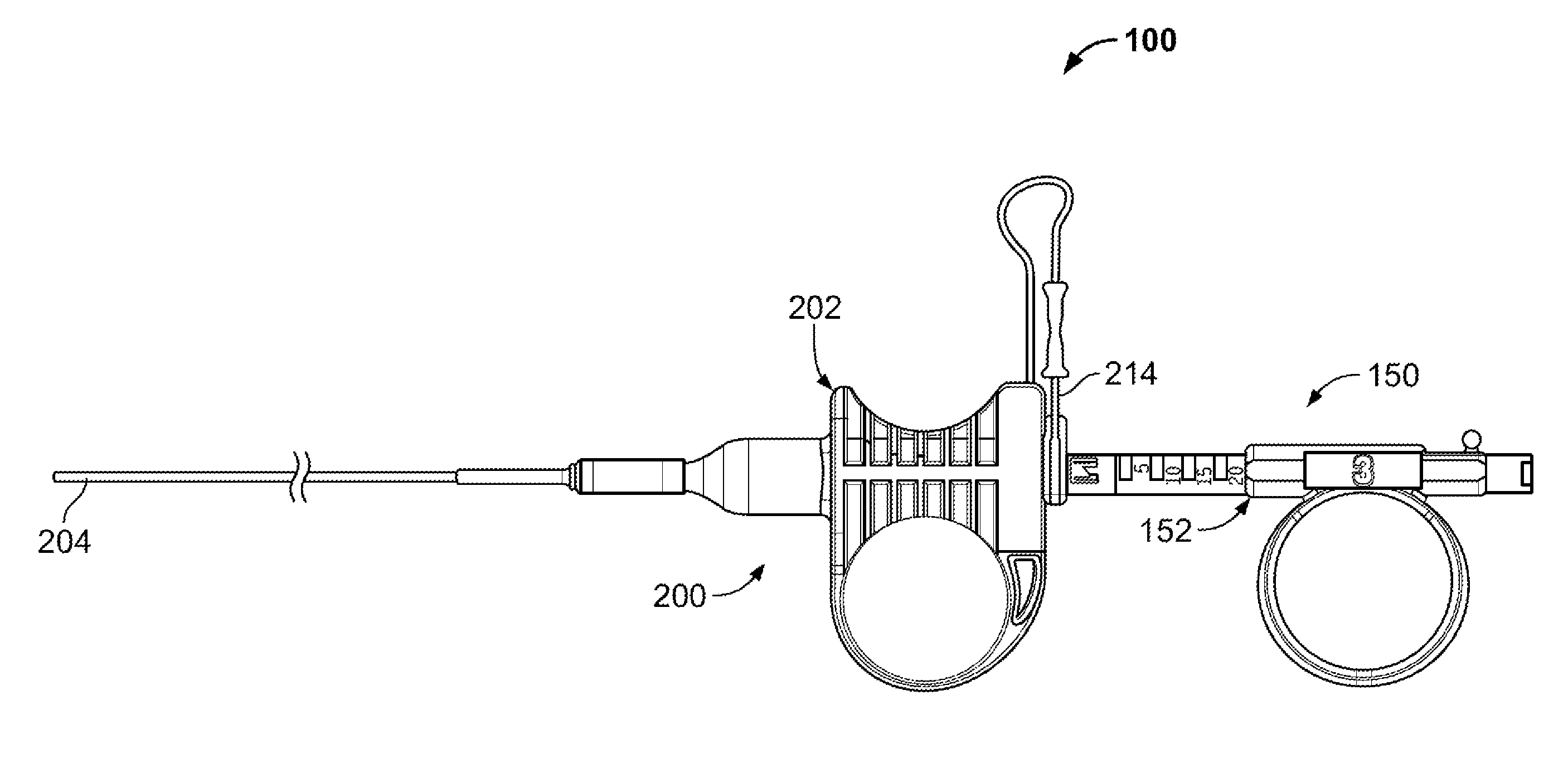
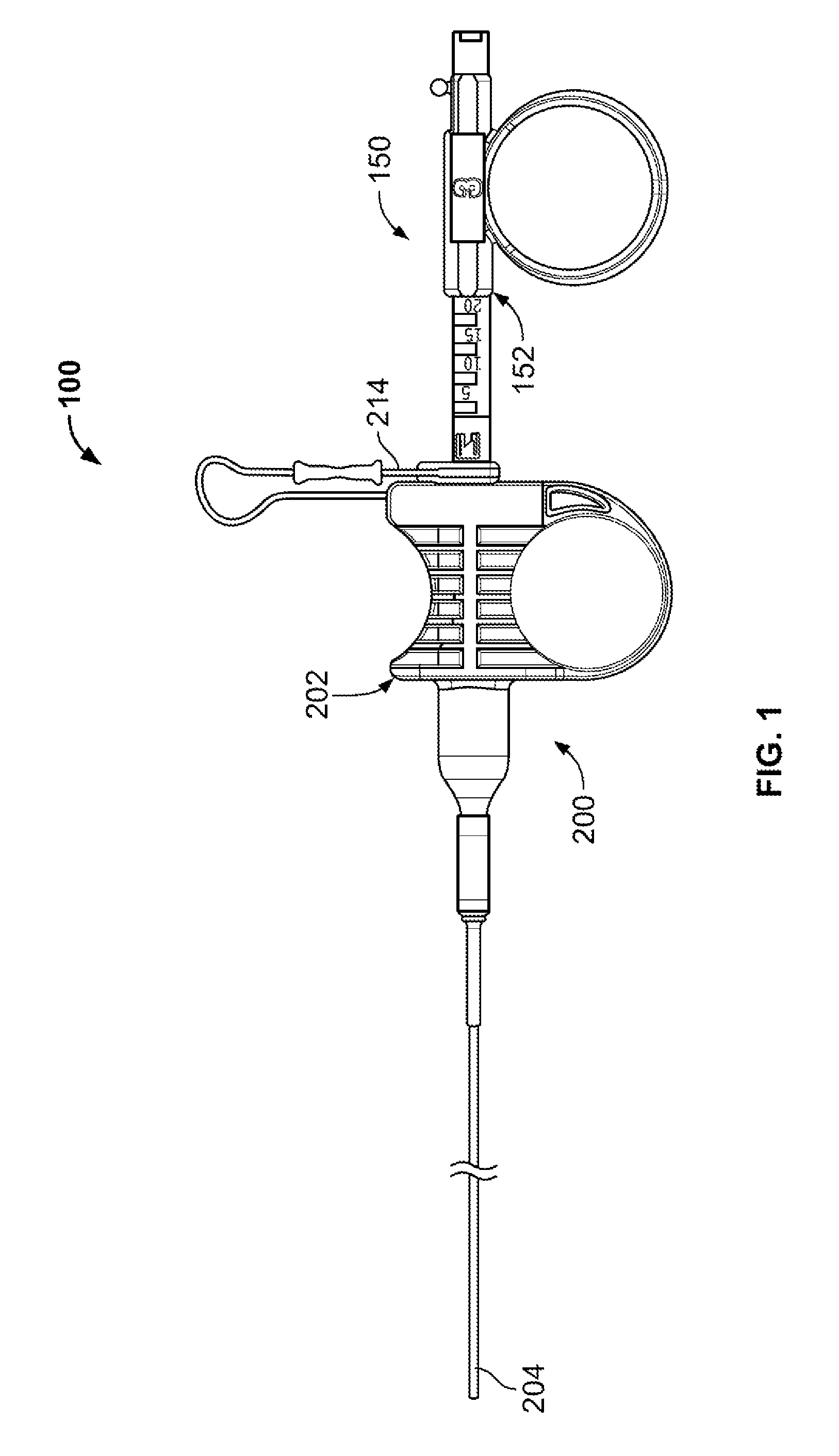
[0043]FIG. 1 illustrates an example of a tissue sampling device 100 having a coring device 150 slidably coupled through a sheath device 200. The coring device 150 includes a coring handle 152 (also referred to as a coring hub) affixed to a shaft (not shown in FIG. 1), where the shaft extends through the sheath device 200. The sheath device 200 includes a sheath handle 202 (also referred to as a sheath hub) affixed to the sheath 204 (typically at a proximal end). The coring handle 152 and the sheath handle 202 are slidably coupled to form a handle assembly of the tissue sampling device 100. In some variations, the coring handle 152 is keyed or otherwise configured so the coring device 150 cannot rotate relative to the sheath 200 or sheath handle 202. As is discussed below, the features of the coring handle 152 and sheath handle 202 provide an advantage when a user actuates the handle to drive the coring device 150 into tissue for capturing a sample of tissue while allowing for contro...


PUM


Abstract

Methods, devices, and systems are described herein that allow for improved sampling of tissue from remote sites in the body. A tissue sampling device comprises a handle allowing single hand operation. In one variation the tissue sampling device includes a blood vessel scanning means and tissue coring means to excise a histology sample from a target site free of blood vessels. The sampling device also includes an adjustable stop to control the depth of a needle penetration. The sampling device may be used through a working channel of a bronchoscope.

Description

CROSS REFERENCE TO RELATED APPLICATION[0001]This application is a non-provisional of prior U.S. Provisional Application No. 61 / 176,859 filed May 8, 2009 and U.S. Provisional Application No. 61 / 229,226 filed Jul. 28, 2009, the entirety of both of which are incorporated by reference.FIELD OF THE INVENTION[0002]The present invention relates to tissue sampling devices and methods that allow sampling of tissue at remote regions in the body where the devices and methods provide improved safety features while also providing configurations that employ ease of use by a physician in a manner similar to a biopsy gun while using a less complex configuration.BACKGROUND[0003]Rapid advancements in medicine are increasingly providing physicians with opportunities to treat medical conditions at an earlier stage leading to an increase in positive outcomes for their patients. Advancements in the fields of pharmaceutical substances, biotechnology, medical procedures as well as medical devices often dri...

Claims


Application Information

Patent Timeline
Patent Type & Authority Patents(United States)
IPC IPC(8): A61B5/00
CPCA61B10/0266A61B10/0283A61B2010/045A61B2019/306A61B2019/4857A61B2019/5278A61B2090/3782A61B2090/0811A61B10/025A61B2090/034A61B2090/036A61B10/04A61B10/06A61B2010/0208A61B2010/0216A61M1/84A61M1/81A61B2010/0258A61B2090/3987A61B1/00165A61B1/018A61B1/2676A61B5/01A61B8/12A61B18/042A61B2018/00577A61B2018/00595A61B2018/00982A61B2018/0212A61B2018/141A61M25/0102A61M25/09A61N5/1007A61N2005/1024
Inventor KEAST, THOMAS M.WEISS, AARON M.GWERDER, ERIC J.SCHWARDT, JEFFREYROSCHAK, EDMUND J.
Owner BRONCUS MEDICAL
Why Eureka
Try Eureka