
Position resolved measurement apparatus and a method for acquiring space coordinates of a quantum beam incident thereon

a quantum beam and measurement apparatus technology, applied in the field of position resolved measurement apparatus and a quantum beam incident thereon acquisition method, can solve the problems of single photon method, small number of electrons that cannot be easily detected nor precisely measured utilizing the current electronic components, and the inability to distinguish single photons, etc., to achieve the improvement of resolution and/or linearity over the field of view of the geometry pattern of different position sensitive detector types, the effect of improving the accuracy of the accuracy of the measurement method

Active Publication Date: 2013-09-10
PHOTONSCORE GMBH +1
View PDF5 Cites 2 Cited by
  • Summary
  • Abstract
  • Description
  • Claims
  • Application Information

AI Technical Summary

Benefits of technology

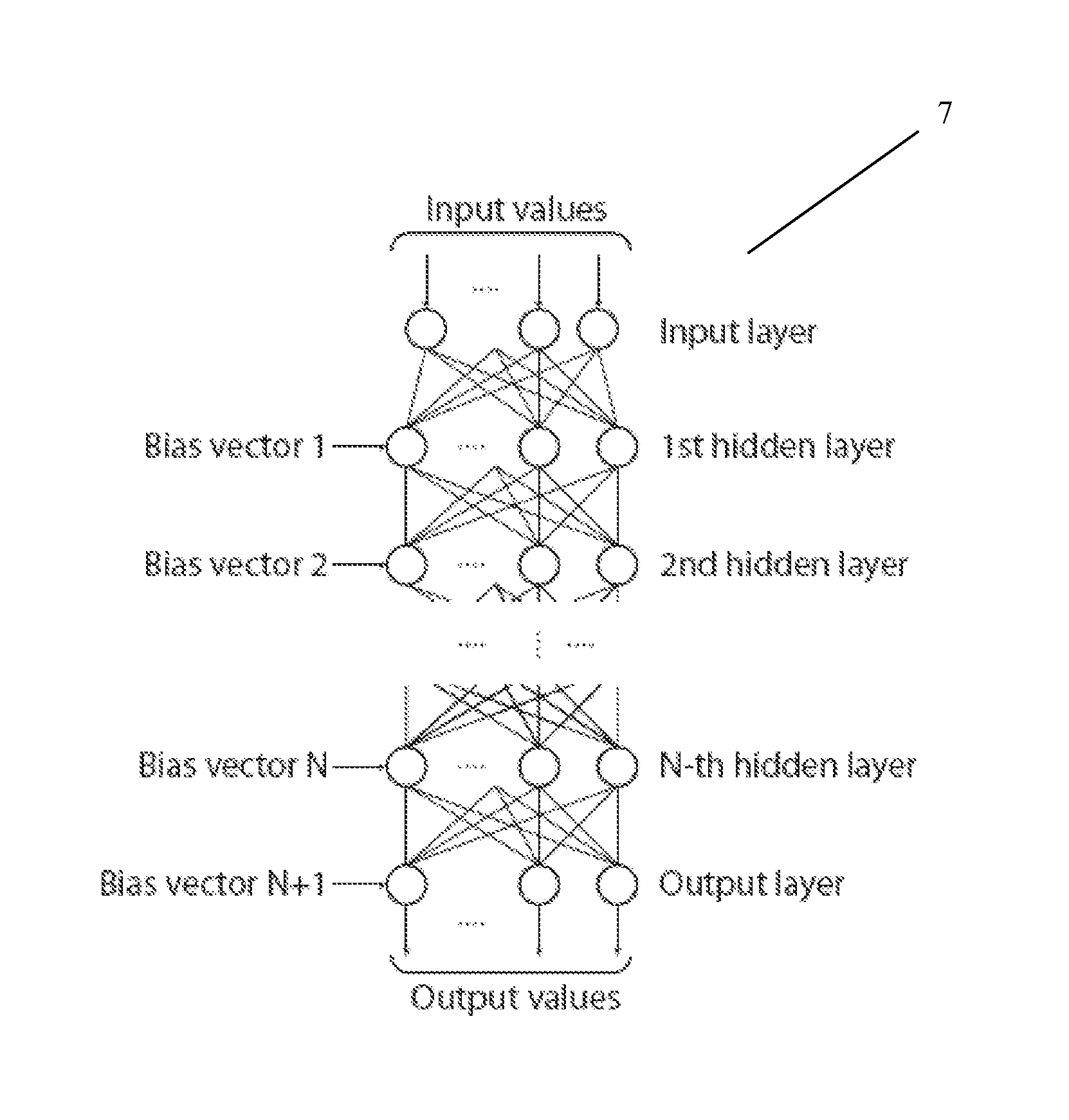
The present invention solves the problem of requiring a heuristic model for estimating by using an artificial neural network. This improves the resolution and linearity of different detector types and reduces the precision requirements for producing an anode. The neural network can easily evaluate the output function. The training process involves storing the detector's response and the known spatial coordinates of irradiation and repeating the process for different spatial coordinates. The technical effects of the invention are more precise position measurements and improved efficiency in position detection.

Problems solved by technology

The amplification leads to a formation of an avalanche of electrons inside the detector resulting in a cloud of electrons inside the detector.
Such a small number of electrons can neither be easily detected nor precisely measured utilizing the current electronic components.
This type of light detection belongs to the integrating measurement class; while it is sensitive enough to register individual quanta of light, the method does not distinguish single photons due to the long-life decay times of the resulting flashes.
An incident particle interacting with the front surface of MCP results in an avalanche of electrons.
However, using stacks of three and more MCPs will result in a shorter lifetime of the detector due to the limited resource of the MCP (amplification degradation).
While the spatial resolution is high, the working area of the approach proposed by Lampton is limited to several millimetres in diameter with respect to the centre point of the quadrants.
This is because the calculation method shown above results in high non-linearity outside the centre of the structure.
However, higher degrees of polynomials suffer the problem of computational non-stability.
Such non-stability is known from the prior art and affects the least square approximation procedure and the computation of the polynomial itself.
These factors make it problematic and practically impossible to employ polynomials to approximate spatial coordinates as a function of the detector responses.
Furthermore, increasing the number of anode outputs will result in a decrease of the final resolution due to the computational errors in the polynomial approximation, while generally a larger number of electrodes in case of charge-division based anode should result in a higher spatial resolution.
If the particle does not hit the sensitive surface of the channel on a first third measured from the front face of the MCP, the event will most probably be lost.
First, if the incident particle is required to hit out a sufficient number of electrons within the first interaction act, the length of the channel will limit the avalanche development.
Gamma-quanta may result a local temperature increase, scattering or hitting out an electron that potentially could result in an avalanche.
The electrons that are born close to the surface or on the surface may be captured by the channel and, probably, result in an avalanche.
This results in a smaller avalanche footprint diameter due to the shorter time span in which internal forces inside the cloud are applied to the individual electrons carrying charge expanding the cloud.
Concluding the above points, it is difficult to find a static or heuristic model of the anode or electron avalanche described in the prior art.

Method used


Image

  • Position resolved measurement apparatus and a method for acquiring space coordinates of a quantum beam incident thereon
  • Position resolved measurement apparatus and a method for acquiring space coordinates of a quantum beam incident thereon
  • Position resolved measurement apparatus and a method for acquiring space coordinates of a quantum beam incident thereon

Examples


example 1

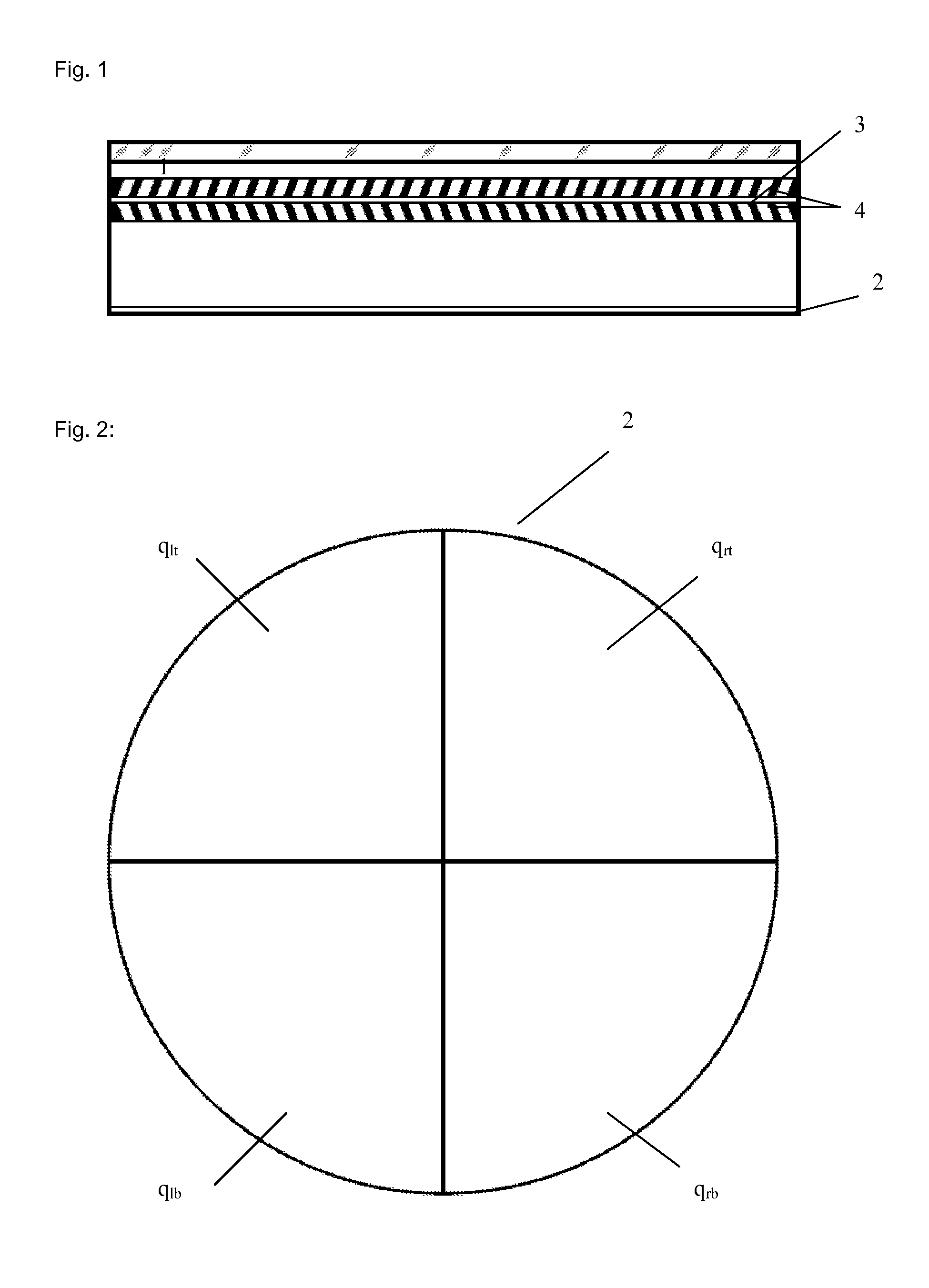
[0220]An example of the neural network training will now be described with reference to an extended quadrant anode detector system allowing an improvement of the image quality of a quadrant anode.

[0221]First of all, the position sensitive detector is described.

[0222]The classical QA described by Lampton demonstrates high resolution down to the diameter of the individual MCP channel. The two major limitations regarding this anode are the strong non-linearity and the small field of view.

[0223]The present invention provides a simple way to overcome the non-linearity problem by applying the ANN apparatus in combination with the calibration procedure.

[0224]The formulas presented by Lampton rely on the ratio equation that is valid in case of complete charge acquisition. As it was demonstrated by Purschke et al, enlarging the quadrants in combination with expanding the avalanche will result in larger a field of view. To build the vacuum-sealed device, it is technologically preferable to us...

example 2

[0267]Moreover, also decoupled multi-segment anodes can be employed. U.S. Pat. No. 5,686,721 discloses the method for isolating the readout anode system from the high-vacuum internal detector volume. The charge of the avalanche is measured directly on the outer surface of the resistive layer outside the detector. This allows one to easily couple an FSA structure.

[0268]In order to apply the method for the charge-image devices, the anode readout pattern was formed on printed circuit board using standard technology. The charge sensitive amplifiers are connected to the open parts of the board. The same calibration procedure as described above is applied.

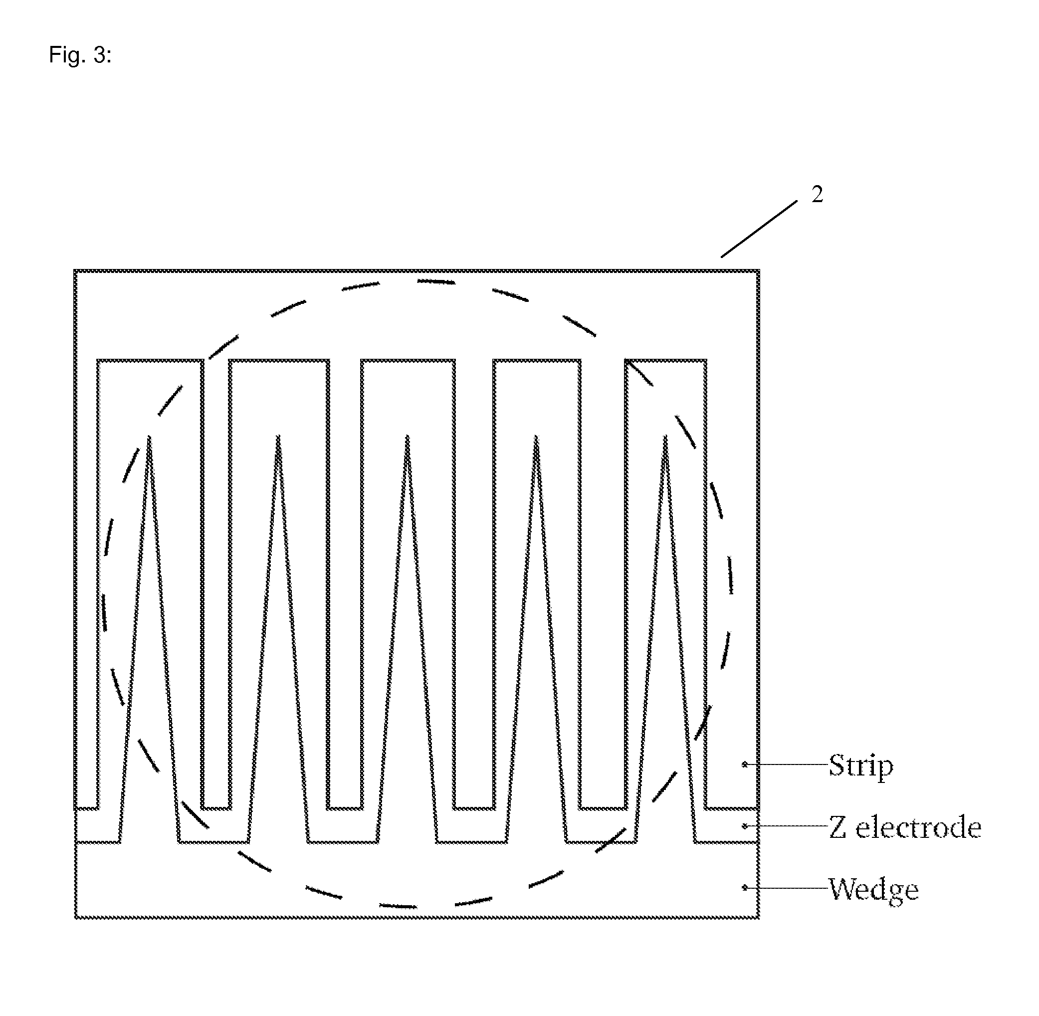
[0269]For the five electrodes structure exactly the same neural network configuration was applied to calculate the coordinate as in case of the vacuum-sealed extended QA anode device.

[0270]For a multi-electrode pattern the network configuration has to be changed. Otherwise the increased number of inputs results in a worsening of the trai...


PUM


Abstract

The position calculation of prior art position sensitive detector systems relies on a known geometry pattern of individual electrodes and the distribution of the charge parts. A heuristic estimation is made in order to calculate an initial coordinate of irradiation. In contrast, the present invention allows one to calculate the position of an incident particle in terms of direct mapping of the measured detector response into position coordinates detector surface. The device for estimating the space coordinates of an irradiation position onto a detector comprises a position sensitive detector; an irradiation source; means for measuring the response of detector generated upon irradiation by irradiation source; and an artificial neural network structure provided such that the measured detector response is the input to the artificial neural network structure and the initial space coordinates of irradiation are the output of the artificial neural network structure.

Description

[0001]This application is a 371 application of PCT / EP2009 / 067564 filed Dec. 18, 2009, which claims foreign priority benefit under 35 U.S.C. §119 of European application 08172354.6 filed Dec. 19, 2008.[0002]The present invention relates to a position resolved measurement apparatus and a method for acquiring position information of an irradiation position of a quantum beam incident thereon, in particular, incident on a position sensitive detector based on an electron multiplication principle with space sensitive readout capability.BACKGROUND OF THE INVENTION[0003]Position sensitive detectors are used to measure spatial coordinates of incident particles thereon. Such particles can be, e.g. photons, electrons, neutrons, ions, x-rays etc. Such detectors are used to detect the particles and their position on a sensitive area of the detector. However, in order to detect individual particles, the signal resulting from that detector needs to be amplified, which may be done, e.g., by an elect...

Claims


Application Information

Patent Timeline
Patent Type & Authority Patents(United States)
IPC IPC(8): G06E1/00G06G7/00G06F15/18G06E3/00
CPCG01T1/2957G01T1/28
Inventor TURBIN, EVGENYPROKAZOV, YURY
Owner PHOTONSCORE GMBH
Learn More