Hand held dispenser

a dispenser and hand-held technology, applied in the field of material dispensers, can solve the problems of affecting the quality of materials, so as to reduce the risk of damage, and minimize the effect of downtim

Active Publication Date: 2013-10-01
PREGIS INTELLIPACK CORP
View PDF29 Cites 13 Cited by
  • Summary
  • Abstract
  • Description
  • Claims
  • Application Information

AI Technical Summary

Benefits of technology

[0028]In a preferred embodiment of the invention the clean-out port diameter on the face of the manifold is dramatically reduced in comparison to what has been done in prior art hand-held dispensers (e.g., dispenser “900 series” hand held dispenser of Sealed Air Corporation located in Saddle Brook, N.J., USA, described above). Also, the mechanism that holds the mixing module in place on the manifold is simplified to make is quite smaller and is placed out of the way on the underside of the mixing module support, thereby minimizing its size and mass and providing contamination protection. Furthermore, placement of the shutoff valves, swivel fittings, and hose connections to the rear of the dispenser also provides for a minimized size in the mechanism involved in holding the mixing module in place on the manifold.
[0067]The problem is addressed in a preferred embodiment of the present invention by designing the input end of the swivel fitting with castellation design. The swivel fitting with inflow and castellation device preferably includes a tapered body with circumferentially spaced projection(s) with adjacent opening(s) which provides for continued flow despite potential abutment of the plug insert at the tip of the heater wire relative to the swivel fitting. This prevents the tip of the heater wire from blocking flow; even if it is pressed in as far as it can go.

Problems solved by technology

Initially, almost all components of a dispenser were built into a single housing, which was relatively bulky.
The single housing dispenser was easy to service or change, but it was an expensive item, as the entire drive mechanism had to be returned for service every time a mixing chamber wore out, or an operator was not able to clean a clogged chemical port.
This quickly became a logistical, and a cost accounting nightmare.
This eliminated the above noted logistical and accounting nightmare, but the customer still had to purchase cartridges whenever they became inoperable, and thus was still a source of expense.
a) Limited to locations that provide compressed air to power them—this would often require the operator to invest in, and install a shop air compressor.
b) Shop air driven power is very inefficient, some estimates put the efficiency factor at 10%. Consequently, it is very expensive to run air-powered equipment.
c) These dispensers did not operate properly if shop air pressure was too low—they will be unable to generate enough force to open the cartridge.
d) Even with adequate air pressure, pneumatic guns have a relatively low opening force, compared to electric drive dispensers that were developed in later years.
e) Cartridges, as they are used, develop a build-up of urethane on the inside diameter (“ID”) of the mixing chamber, which gradually increases the level of force required to open the cartridge. Consequently, the relatively low opening force limits the service life of the cartridge, since it is useless if it can no longer be opened by the drive system.
f) Air driven dispensers are sensitive to water in the air supply lines—which can wash the lubrication out of the sliding seals—and leak into the A chemical container from the pumps, and also are sensitive to oil and rust in the compressed air supply lines.
g) These prior art pneumatic dispensers are also not robust in the workplace, and required frequent maintenance and repair.
In most settings, the problems associated with these air driven systems were deemed by the operators to outweigh the advantages.
The electric driven hand held dispensers thus have some advantages over the air driven systems in avoiding some of the above noted problems associated with air driven systems, but the electric driven systems (as well as many other current hand held dispenser designs in general) also suffer from a variety of drawbacks.
For example, the placement and / or sizing of components of many of the prior art designs as in the shutoff valves, swivel fittings, port plug and filter screens provide for a bulky, non-slender handheld design with associated drawbacks as in poor operator ergo-dynamics (e.g., poor balancing in hand), poor visibility and container accessing limitations, as well as high susceptibility to chemical contamination of dispensed product build-up on those components.
Additionally, many of the prior art designs involve small area filter elements and typical electric driven hand held dispensers are prone to failure as in freewheeling failures and gear failures, lack of sufficient power to avoid freeze ups despite having driving systems that often present bulky and excessive component drive transmissions.
Additional drawbacks associated with typical conventional designs include non-robust trigger switches, poor electrical power line dispenser connections, poor chemical heater performance (when provided at all) in the hand held dispenser, low volume solvent feeding systems and inefficient mixing module mounting systems.

Method used


Image

  • Hand held dispenser
  • Hand held dispenser
  • Hand held dispenser

Examples


Embodiment Construction

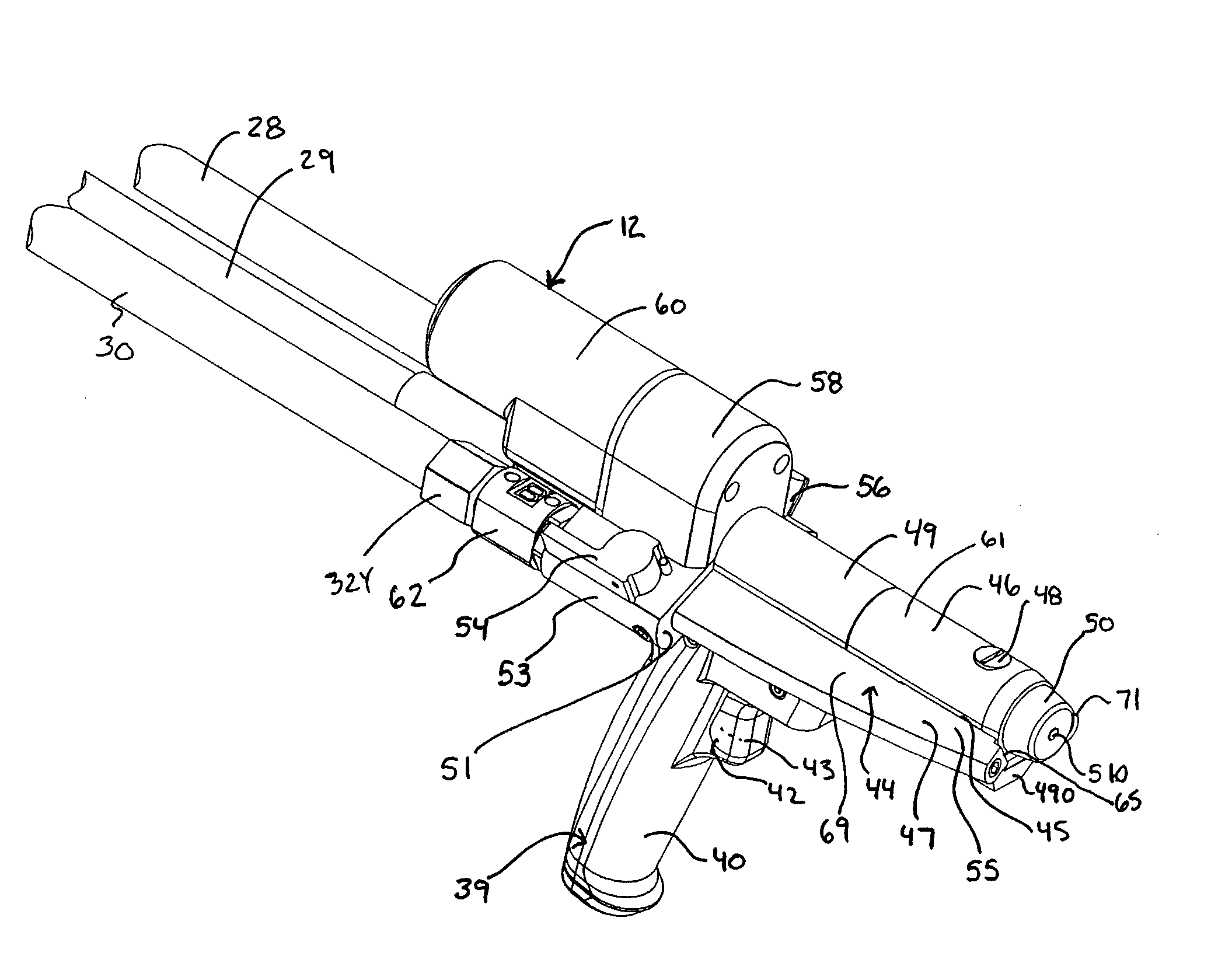
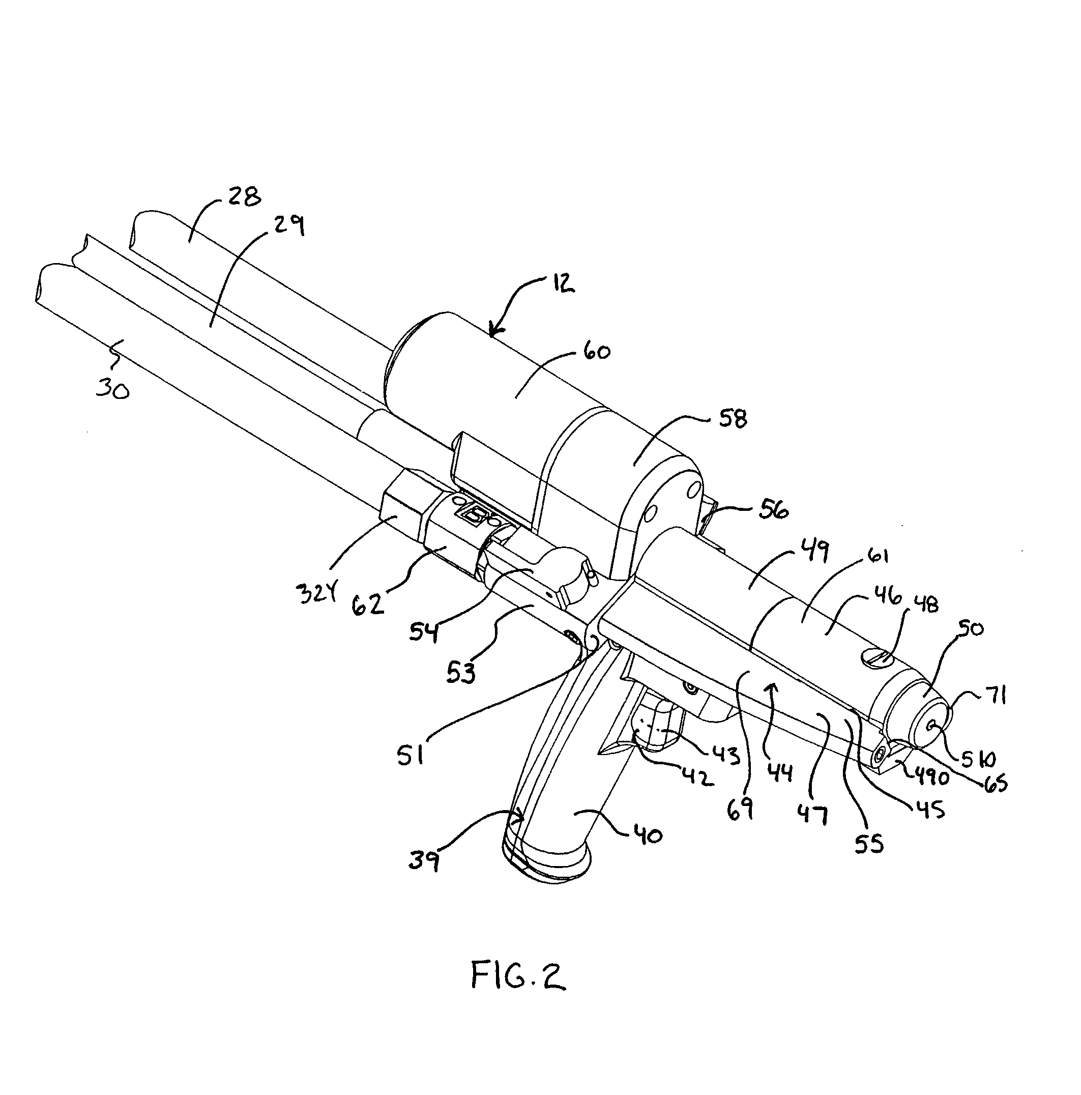
[0109]The following disclosure describes various renderings of preferred embodiments of a dispenser system and hand held dispenser which are featured under the subject mater of the present invention.

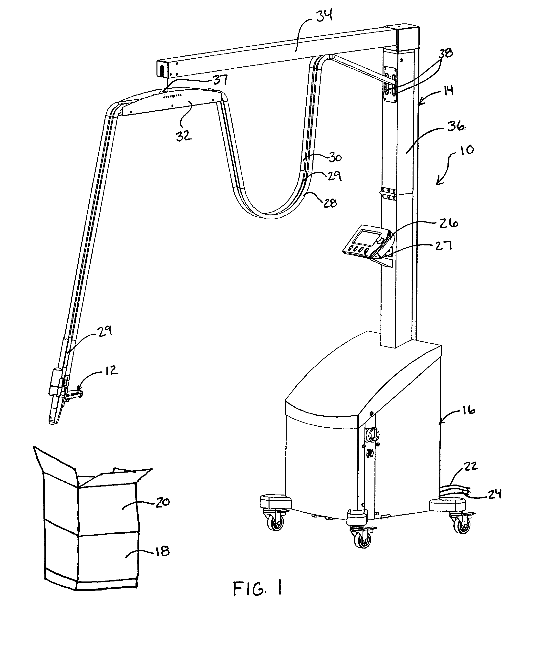
[0110]FIG. 1 shows dispenser system 10 with hand held dispenser 12, means for supporting the hand held dispenser 14 and base unit 16. In the illustrated embodiment, base unit 16 provides a housing for components of the supply means for providing a supply of dispenser material to the hand held dispenser. For example, base unit 16 houses a pump system as in a pair of “in-line” pump assemblies such as the gerotor pumps exemplified in PCT publication WO 2004 / 101245 to Intellipack of Tulsa Okla., USA. These pumps (not shown) receive foam precursor chemical from chemical source lines 22, 24 feeding into base unit 16 and connected at origination end to chemical A and chemical B sources as in chemical drums or larger containers. Various other chemical feed systems for feeding chemical to, from a...


PUM

PropertyMeasurementUnit
pitch angleaaaaaaaaaa
lengthaaaaaaaaaa

Abstract

A hand held dispenser system with associated dispensed material supply assembly as in separate source chemical foam precursor feeding into, for example, streamlined chemical passageways preferably each comprised of, in series, a castellated swivel hose filter, a valve assembly housing, a wing extensions of a manifold, which manifold supports a high efficiency drive system and is supported by a handle that provides for a compact assembly and receives a rugged trigger assembly. The manifold design provides for elongated filter and, temperature controlled cartridge heater insertion. There is further provided in a preferred embodiment a readily releasable electric source feed line plug connection at the butt end of the dispenser. The dispenser is well suited for the dispensing of methane foam as in a product packaging setting.

Description

CROSS REFERENCE TO RELATED APPLICATIONS[0001]The present application claims priority to U.S. Provisional Patent Application No. 60 / 552,207, filed Mar. 12, 2004 which is incorporated herein by reference in its entirety.BACKGROUND[0002]A variety of material dispensers have been developed including those directed at dispensing foamable material such as polyurethane foam which involves mixing certain chemicals together to form a polymeric product while at the same time generating gases such as carbon dioxide and water vapor. If those chemicals are selected so that they harden following the generation of the carbon dioxide and water vapor, they can be used to form “hardened” (e.g., a cushionable quality in a proper fully expanded state) polymer foams in which the mechanical foaming action is caused by the gaseous carbon dioxide and water vapor leaving the mixture. In particular techniques, synthetic foams such as polyurethane foam are formed from liquid organic resins and polyisocyanates...

Claims


Application Information

Patent Timeline
Patent Type & Authority Patents(United States)
IPC IPC(8): B67D7/78B29B7/74
CPCB29B7/7438Y10T29/49826B29K2105/04B29K2075/00
Inventor BERTRAM, GEORGEWALKER, DOUGLASHAYDUK, MATTHEW
Owner PREGIS INTELLIPACK CORP
Why Eureka
Try Eureka