Fuel rail assembly including fuel separation membrane

a technology of separation membrane and fuel rail, which is applied in the direction of special fuel injection apparatus, machines/engines, process and machine control, etc., can solve the problems of reducing the effective size of the separator, fuel separation rate, and impairing engine performance, so as to improve the separation rate of fuel mixture, reduce cost and other associated packaging constraints, and increase the fuel separation rate

Inactive Publication Date: 2013-10-08
FORD GLOBAL TECH LLC
View PDF266 Cites 30 Cited by
  • Summary
  • Abstract
  • Description
  • Claims
  • Application Information

AI Technical Summary

Benefits of technology

[0001]Internal combustion engines utilizing two or more different fuels have been proposed. As one example, the papers titled “Calculations of Knock Suppression in Highly Turbocharged Gasoline / Ethanol Engines Using Direct Ethanol Injection” and “Direct Injection Ethanol Boosted Gasoline Engine: Biofuel Leveraging for Cost Effective Reduction of Oil Dependence and CO2 Emissions” by Heywood et al. describe engines that are capable of using multiple fuels. Specifically, the Heywood et al. papers describe directly injecting ethanol into the engine cylinders to improve charge cooling effects, while relying on port injected gasoline to providing a majority of the combusted fuel over a drive cycle. The ethanol, in this example, can provide increased octane and increased charge cooling due to its higher heat of vaporization in comparison to gasoline, thereby reducing knock limits on boosting and / or compression ratio. This approach purports to improve fuel economy and increase utilization of renewable fuels.
[0005]By placing the fuel separation membrane within the fuel rail assembly, which is in relative close proximity to the engine, the fuel separation membrane and the fuel mixture to be separated by the membrane can be at least partially heated by the engine. In this way, the fuel separation rate can be increased without requiring a separate heater, thereby reducing cost and other associated packaging constraints. Further, in this way, it is possible to utilize a fuel pump to pressurize fuel for injection to the engine, as well as for improved separation of the fuel mixture.
[0006]The inventors herein have also recognized that the fuel separation rate can be further increased by increasing the surface area of the fuel separation membrane relative to the volume of the separator. As one example, the surface area of the membrane may be increased for a given separator volume by supporting the membrane on a substrate that forms a non-planar membrane element within the fuel rail, such as a tube. By supplying the pressurized fuel to the external surface of the tubular membrane element, the substrate can be loaded in compression, which can provide an additional strength advantage for some substrate materials such as ceramics or other materials that are relatively stronger when loaded in compression than tension.
[0007]The inventors herein have also recognized that a plurality of separate membrane elements within a common fuel rail assembly can further increase the separation rate for a given separator volume. For example, by utilizing multiple smaller tubes for the membrane elements, the ring stress in the substrate can be reduced, thereby enabling a further reduction in wall thickness of the substrate. A reduction in wall thickness and increased surface area of the membrane elements can further increase the fuel separation rate while also reducing packaging constraints. These and other advantages will be appreciated in light of the following specification and accompanying drawings.
[0008]In still another embodiment, a method of operating a fuel system for an internal combustion engine may be used, comprising: supplying a pressurized fuel mixture to a fuel rail, said fuel mixture including a hydrocarbon component and an alcohol component; separating at least a portion of the alcohol component from the fuel mixture by passing at least said portion of the alcohol component through a fuel separation membrane element disposed within the fuel rail to obtain an alcohol reduced fuel mixture; delivering the alcohol reduced fuel mixture from the fuel rail to at least a plurality of cylinders of the engine via injectors fluidly coupled with the first fuel rail; and supplying the separated alcohol component to the engine. In this way, it is possible to utilize a fuel pump to pressurize fuel for injection to the engine, as well as for improved separation of the fuel mixture.

Problems solved by technology

However, the inventors herein have recognized a variety of issues associated with the approach taken by Usami et al.
As one example, the inventors have recognized that engine packaging constraints on-board a vehicle may preclude the addition of a fuel separator or may reduce the effective size of the separator.
A reduction in the separator size can reduce fuel separation rates, which may in turn impair engine performance where the fuel to be separated is temporarily unavailable or available in a reduced amount due to the reduced separation rate.
As another example, the use of a dedicated heater as taught by Usami et al. to improve the separation rate by way of heat addition is also limited by the similar packaging constraints.

Method used


Image

  • Fuel rail assembly including fuel separation membrane
  • Fuel rail assembly including fuel separation membrane
  • Fuel rail assembly including fuel separation membrane

Examples


Embodiment Construction

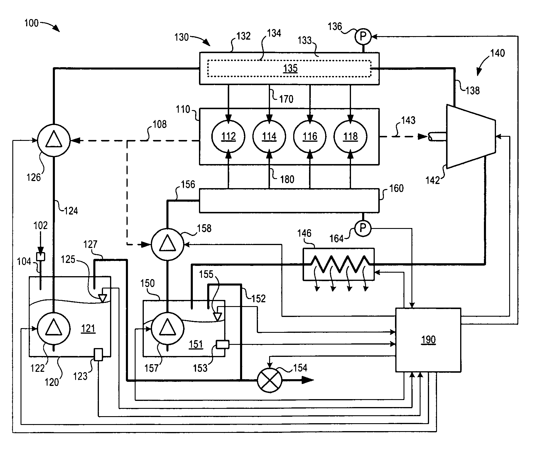
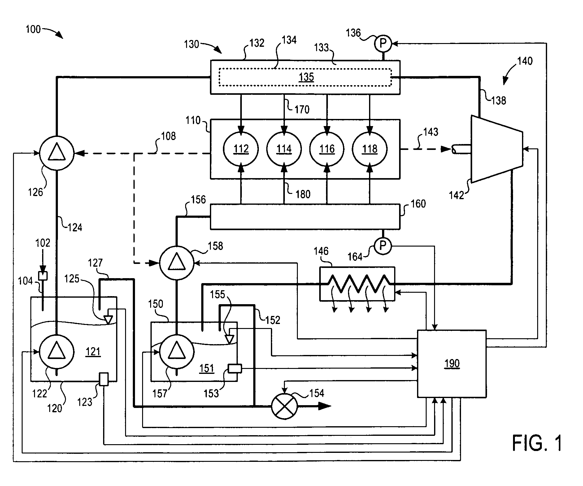
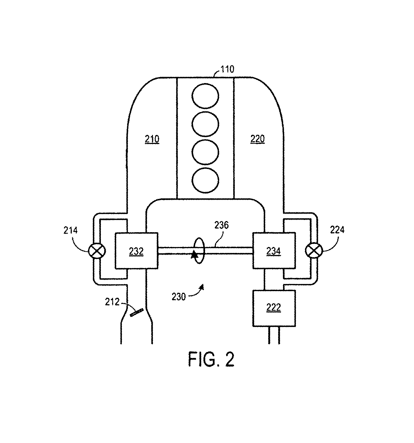
[0019]FIG. 1 shows a schematic depiction of an example fuel system 100 for a fuel burning engine 110. As one non-limiting example, engine 110 can be configured as an internal combustion engine that is configured on-board a vehicle as part of a propulsion system. However, engine 110 can include other engine types and can be configured in other suitable applications. In this particular example, engine 110 includes four combustion chambers or cylinders indicated at 112, 114, 116, and 118. In other examples, engine 110 may include any suitable number of cylinders. Engine 110 will be described in greater detail with reference to FIGS. 2 and 3.

[0020]In this example, each cylinder of engine 110 can receive at least two separate fuels having different compositions in varying relative amounts based on operating conditions. Thus, each engine cylinder can receive a first fuel as indicated at 170 via a first fuel rail assembly 130 and can receive a second fuel indicated at 180 via a second fuel...


PUM


Abstract

As one example, a fuel rail assembly for supplying pressurized fuel to a plurality of cylinders of an engine is provided. The fuel rail assembly includes a fuel rail housing defining an internal fuel rail volume having at least a first region and a second region; a fuel separation membrane element disposed within the fuel rail housing that segregates the first region from the second region. The membrane element can be configured to pass a first component of a fuel mixture such as an alcohol through the membrane element from the first region to the second region at a higher rate than a second component of the fuel mixture such as a hydrocarbon. The separated alcohol and hydrocarbon components can be provided to the engine in varying relative amounts based on operating conditions.

Description

BACKGROUND AND SUMMARY[0001]Internal combustion engines utilizing two or more different fuels have been proposed. As one example, the papers titled “Calculations of Knock Suppression in Highly Turbocharged Gasoline / Ethanol Engines Using Direct Ethanol Injection” and “Direct Injection Ethanol Boosted Gasoline Engine: Biofuel Leveraging for Cost Effective Reduction of Oil Dependence and CO2 Emissions” by Heywood et al. describe engines that are capable of using multiple fuels. Specifically, the Heywood et al. papers describe directly injecting ethanol into the engine cylinders to improve charge cooling effects, while relying on port injected gasoline to providing a majority of the combusted fuel over a drive cycle. The ethanol, in this example, can provide increased octane and increased charge cooling due to its higher heat of vaporization in comparison to gasoline, thereby reducing knock limits on boosting and / or compression ratio. This approach purports to improve fuel economy and i...

Claims


Application Information

Patent Timeline
Patent Type & Authority Patents(United States)
IPC IPC(8): F02B13/00F02M37/00
CPCF02M63/0225F02M69/50F02D19/0605F02D19/081F02M37/0064F02M37/0088F02M43/00F02M55/025F02D19/0665F02D19/0671F02D19/0689F02D19/0692Y02T10/36F02D35/02F02D35/027F02M2200/27Y02T10/30F02D41/0025F02M69/465F02D19/08
Inventor PURSIFULL, ROSS DYKSTRADEARTH, MARK ALLENLEONE, TOM G.
Owner FORD GLOBAL TECH LLC
Why Eureka
Try Eureka