Method and apparatus for waveform generation

a waveform generator and radio frequency lightwave technology, applied in multiplex communication, instruments, optics, etc., can solve the problems of noise, difficult for the interceptor to distinguish the signal from the background noise, and difficult for the receiver to detect the signal

Active Publication Date: 2013-10-08
HRL LAB
View PDF4 Cites 16 Cited by
  • Summary
  • Abstract
  • Description
  • Claims
  • Application Information

AI Technical Summary

Benefits of technology

[0027]Embodiments of the present invention make use of the wideband nature of photonics to generate dense, frequency-spread, comb waveforms. The total bandwidth of the comb can be quite wide, with several GHz bandwidths easily achieved by the photonic methods according to embodiments of the present invention. The finely spaced tones are produced by frequency modulation using an electronic method, which has fine frequency resolution. Embodiments of the present invention also make use of the properties of optical injection locking and heterodyning to frequency modulate a comb of many tones.
[0038]In yet another aspect, an embodiment of the present invention provides an apparatus for generation of frequency modulated, multi-tone waveforms (especially pulses) and an apparatus for pre-processing of such waveforms. The frequency modulated, multi-tone waveform generated can further be amplitude-modulated with a pulse code and can serve as a Transmit waveform for a radar system. The pre-processor processes the Receive waveform or radar return signal. The preprocessing effectively creates multiple short pulses from a single long pulse and combines the information from those short pulses.
[0039]According to the yet another aspect, embodiments of the present invention have a generator which applies frequency modulation to a multi-tone RF carrier waveform. In one embodiment, a periodic electronic frequency modulation is combined with multi-tone generation by a photonic oscillator to produce a dense frequency-spread comb that has both fine comb spacing and large overall bandwidth. The density of this comb is greater than the density of combs generated with prior approaches. Such a dense, multi-tone Transmit waveform has low probability of being detected by an electronic intercept receiver. In another embodiment, frequency modulation by a single-value invertible (SVI) function is combined with multitone generation by a photonic oscillator to encode different temporal portions of the waveform so that the portions are distinct from each other. Such a frequency-encoded waveform can be combined with a suitable receiver to achieve temporal compression of a pulsed frequency spread comb. The generator can make use of the frequency selection property arising from the finite injection-locking bandwidth and short response lifetime of optical-injection locked lasers. A master laser is amplitude-modulated by an electronic frequency-modulated RF tone. Two slave lasers that are coupled to the master laser are biased to select, respectively, the optical carrier of the master laser and the RF-modulated sideband. The output of one slave laser has a wavelength that is modulated according to the electronic frequency modulation and represents the first RF-lightwave signal. The output of the other slave laser is fed to an optical comb generator, which amplitude-modulates onto that optical carrier a comb of tones. This second RF-lightwave signal is a frequency spread signal with tones separated by a coarse spacing but covering a large bandwidth. These two RF-lightwave signals are then combined by optically heterodyning them at one or more photodetectors.
[0042]In still another aspect, a Receiver contains a pre-processor that achieves pulse compression of the multi-tone waveforms. The pre-processing achieves temporal division of the multi-tone Transmit reference carrier waveform and the Receive (or radar return) waveform into series of segments. This feature permits multiple time-staggered sets of the Transmit reference segments to be made. These reference segments may then be used for comparison with the Receive waveform segments. By repeatedly presenting segments of the Transmit reference waveform for the comparison, a priori knowledge of the approximate radar target range (distance) is obviated. Yet another unique feature is the filters used to spectrally separate the multiple tones of the Transmit reference and Receive waveforms for their comparison by RF mixing. This comparison preferably occurs on a tone-by-tone basis or with small subsets of tones. These filters preferably have a periodic frequency spectrum. By using two sets of such filters with each set having a different spectral period, fewer filters are needed to accommodate the large number of distinct frequencies that must be separated. Also, a novel configuration of tapped delay lines and RF switches are preferably used to temporally align the Receive segments with the repeated Transmit-reference.

Problems solved by technology

Multi-tone frequency spreading may be used to make the resultant signal difficult for a non-coherent receiver to detect.
However, if the signal is spread in frequency so those portions of it fall within many channels, it is difficult for the interceptor to distinguish that signal from the background noise.
If the signal frequency is varied rapidly to move between different channels within the sensing time, it also appears like noise.
Alternatively, if the signal frequencies are varied rapidly with time although those hops lie within the received channels, that signal will be detected but difficult to identify.
However, frequency modulation to compress a multi-tone pulse has been difficult to accomplish.
Frequency modulation of a large number of tones has previously been cumbersome and expensive to implement.
However, long pulses have poor resolution of the target range, since returns that occur within a given pulse duration are not distinguishable.

Method used


Image

  • Method and apparatus for waveform generation
  • Method and apparatus for waveform generation
  • Method and apparatus for waveform generation

Examples


Embodiment Construction

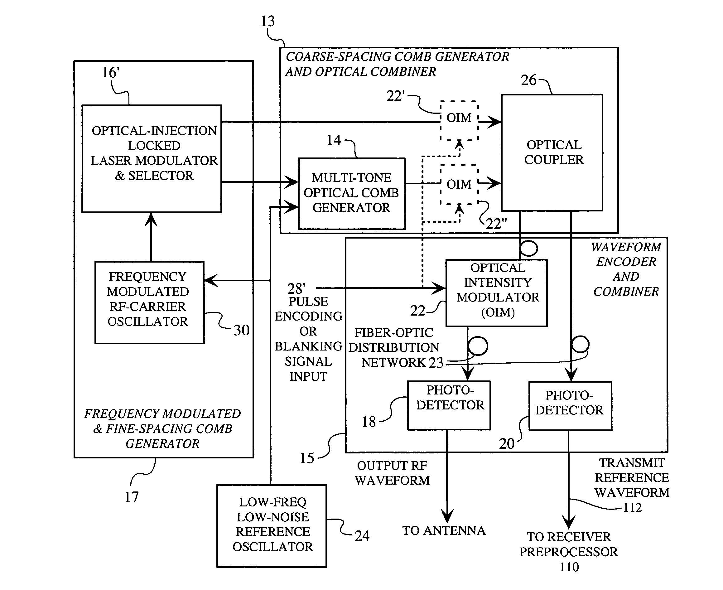
[0068]This invention relates to a unique approach in the generation of rapidly frequency hopped or dithered, or frequency modulated multi-tone RF comb lines on a lightwave carrier using coherent optical heterodyning in order to make the signal transmitted on these carriers difficult to detect. The concept of optical heterodyning was briefly discussed above, to provide background information. Two embodiments for generating a frequency translatable comb signal are described with reference to FIGS. 3-6. Then, several embodiments for producing a frequency-hopped waveform are described with reference to FIGS. 7 and 8. Finally, modifications for improved stability and tone uniformity are then discussed (with reference to FIGS. 9-14) according to embodiments for generating the frequency translatable comb signal.

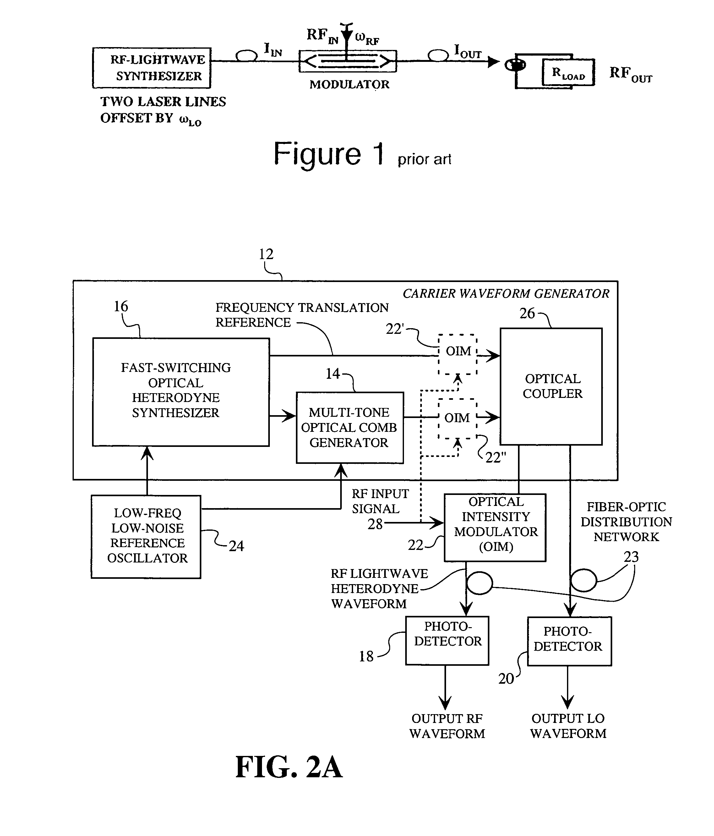
[0069]A block diagram of an agile waveform generator 12 according to an embodiment of the present invention is shown in FIG. 2A. The embodiment depicted in FIG. 2A may be particular...


PUM

PropertyMeasurementUnit
frequencyaaaaaaaaaa
lengthaaaaaaaaaa
frequencyaaaaaaaaaa

Abstract

A spread spectrum waveform generator has a photonic oscillator and an optical heterodyne synthesizer. The photonic oscillator is a multi-tone optical comb generator for generating a series of RF comb lines on an optical carrier. The optical heterodyne synthesizer includes first and second phase-locked lasers, where the first laser feeds the multi-tone optical comb generator and the second laser is a single tone laser whose output light provides a frequency translation reference. At least one photodetector is provided for heterodyning the frequency translation reference with the optical output of the photonic oscillator to generate a spread spectrum waveform. A receiver pre-processor may be provided to operate on the spread spectrum waveform.

Description

CROSS REFERENCE TO RELATED APPLICATIONS[0001]This application is a divisional application of 10 / 824,197 filed Apr. 13, 2004.[0002]This application is a continuation-in-part and claims the benefit of International Application No. PCT / US02 / 36849, filed Nov. 15, 2002, which is a continuation-in-part and claims the benefit of U.S. application Ser. No. 10 / 116,829, filed Apr. 5, 2002, which claims the benefit of U.S. Provisional Application No. 60 / 332,372, filed Nov. 15, 2001. The entire contents of International Application No. PCT / US02 / 36849, U.S. application Ser. No. 10 / 116,829, and U.S. Provisional Application No. 60 / 332,372 are hereby incorporated by reference herein.[0003]This application is also a continuation-in-part and claims the benefit of International Application No. PCT / US02 / 36982, filed Nov. 15, 2002, which is a continuation-in-part and claims the benefit of U.S. application Ser. No. 10 / 116,829, filed Apr. 5, 2002, which claims the benefit of U.S. Provisional Application No...

Claims


Application Information

Patent Timeline
Patent Type & Authority Patents(United States)
IPC IPC(8): H04B10/00G02F2/00H01S3/067H03B21/02H03B28/00H04B10/04H04B10/12H04B10/50H04J13/06H04J14/00
CPCG02F2/02H03B21/02H03B28/00H04B10/505H01S3/0057
Inventor YAP, DANIELSAYYAH, KEYVAN
Owner HRL LAB
Why Eureka
Try Eureka