Wheel bearing apparatus and axle module

a technology of axle module and bearing device, which is applied in the direction of bearing unit rigid support, couplings, transportation and packaging, etc., can solve the problems of low transferability of rotation torque, high cost, and high cost, and achieves easy adjustment of hardening condition, reduced oxidation, and reduced hardening distortion

Active Publication Date: 2013-10-15
NTN CORP
View PDF19 Cites 22 Cited by
  • Summary
  • Abstract
  • Description
  • Claims
  • Application Information

AI Technical Summary

Benefits of technology

[0050]The projections can be hardened by heat hardening treatment, that is, by high-frequency heat treatment. Thus, the following advantages of the high-frequency heat treatment can be realized (local heating can be performed and hardening condition can be easily adjusted; oxidation is reduced because heating can be performed in a short period of time; hardening distortion is reduced in comparison with other methods; surface hardness is high and excellent wear resistance can be obtained; selection of the depth of the hardened layer is relatively easy; and automation is easily realized and assembly into a machine process line can be realized). In particular, high compressive residual stress can be applied by combining the shot peening with the high-frequency heat treatment, and thus improvement of fatigue strength can be expected.
[0051]By setting the circumferential thickness of the projecting direction intermediate region of each of the projections to be smaller than a dimension at the position corresponding to the intermediate region between the projections adjacent to each other in the circumferential direction, it is possible to increase the circumferential thickness of the projecting direction intermediate region of each of the projections on the side in which the recesses are formed (projections among the formed recesses). Therefore, it is possible to increase a shearing area of each of the projections on the opposite side (projections having low hardness among the recesses because the recesses are formed) and secure torsion strength. Moreover, because a tooth thickness of the projections on the high hardness side is small, it is possible to reduce press-fitting load and realize improvement of press-fitting properties.
[0052]Further, when the recess-projection fitting structure allows separation by application of the drawing force in the axial direction with respect to the shaft section of the outer joint member, the outer joint member can be removed from the hole of the hub wheel, and after being removed, can be press-fitted therein again. Therefore, it is possible to more easily perform maintenance, repairing, inspection, replacement work of the components of the wheel bearing device. In addition, it is possible to replace only the components necessary to be replaced, and to save component replacement cost for maintenance and repairing. Therefore, a low-cost wheel bearing device can be provided.
[0053]When the positioning inner wall is provided and positioning is performed thereby, dimension accuracy of this wheel bearing device is stabilized, and it is possible to secure a stable length as an axial length of the recess-projection fitting structure disposed along the axial direction and realize improvement of torque transmission performance.
[0054]With the shaft section slip-off preventing structure, it is possible to effectively prevent the shaft section of the outer joint member from slipping off in the axial direction from the hole of the hub wheel. Consequently, it is possible to maintain a stable connected state and realize improvement of a quality of the wheel bearing device. Further, a diameter expansion work can be more easily performed when the end expanded-diameter caulking section is unsubjected to hardening treatment.
[0055]The axle module in which the wheel bearing device as described above is used can be manufactured by small work man-hours and assembly man-hours. When deficiencies leading to replacement of the wheel bearing device occur, it is possible to separate this wheel bearing device from the knuckle, separate the wheel bearing and the constant-velocity universal joints from each other, replace only the components necessary to be replaced, and save component replacement cost for maintenance and repairing. In particular, by setting the maximum outer diameters of the outboard-side constant-velocity universal joint and the inboard-side constant-velocity universal joint to be smaller than the outer diameter of the outer member of the wheel bearing of the wheel bearing device, those constant-velocity universal joints can be easily caused to pass with respect to the knuckle. Therefore, assemblability of the axle module can be improved.

Problems solved by technology

Therefore, because it is necessary to apply spline machining to both spline sections on the shaft section 173 side and on the hub wheel 152 side, cost increases.
In this case, if the shaft section 173 is press-fitted into the hub wheel 152 by aligning tooth surfaces thereof, recessed and projected teeth are likely to be damaged (torn).
If the backlash occurs in the circumferential direction in this way, transferability of rotation torque is low and abnormal noise tends to occur.
Therefore, when the shaft section is press-fitted into the hub wheel by the spline fitting as in the prior art, it is difficult to remove damages to the recessed and projected teeth and the backlash in the circumferential direction at the same time.
Incidentally, even if adhesiveness of a male spline and a female spline is improved in the spline fitting to prevent the backlash in the circumferential direction from occurring, if driving torque acts, it is likely that relative displacement occurs in the male spline and the female spline.
If such relative displacement occurs, fretting wear occurs.
The splines are likely to cause abrasion because of dust of the wear.
Consequently, it is likely that a backlash occurs in a spline fitting region or stable torque transmission cannot be performed.
However, reliability of a slip-off preventing effect is low only with such press fitting.
When the snap ring is used, at the time of maintenance, repairing, and the like, it is difficult to dismount the outer member from the knuckle and high drawing load is inevitably applied for disassembly.
As a result, because a snap ring groove of the knuckle is broken, the knuckle also needs to be replaced, which involves higher cost of maintenance and repairing.

Method used


Image

  • Wheel bearing apparatus and axle module
  • Wheel bearing apparatus and axle module
  • Wheel bearing apparatus and axle module

Examples


second embodiment

[0188]FIG. 16 illustrates a The shaft section slip-off preventing structure M1 of the wheel bearing device is configured by providing a tapered locking piece 70 that projects to the outer diameter direction in a part of the shaft section 12 rather than forming the short cylindrical section 66 illustrated in FIG. 5 in advance.

[0189]In this case, a jig 71 illustrated in FIG. 17 is used. The jig 71 includes a columnar main body section 72 and a short cylindrical section 73 connected to a distal end of the main body section 72. A small-diameter step section 74 is provided at a distal end of an outer peripheral surface of the short cylindrical section 73. Therefore, a distal end wedge section 75 is formed in the jig 71. As illustrated in FIG. 18, if the distal end wedge section 75 is driven (load in the arrow a direction is applied) to an end surface 12c of the shaft section 12, a sectional shape of the distal end wedge section 75 on the outer diameter side is a tilting surface, and the...

third embodiment

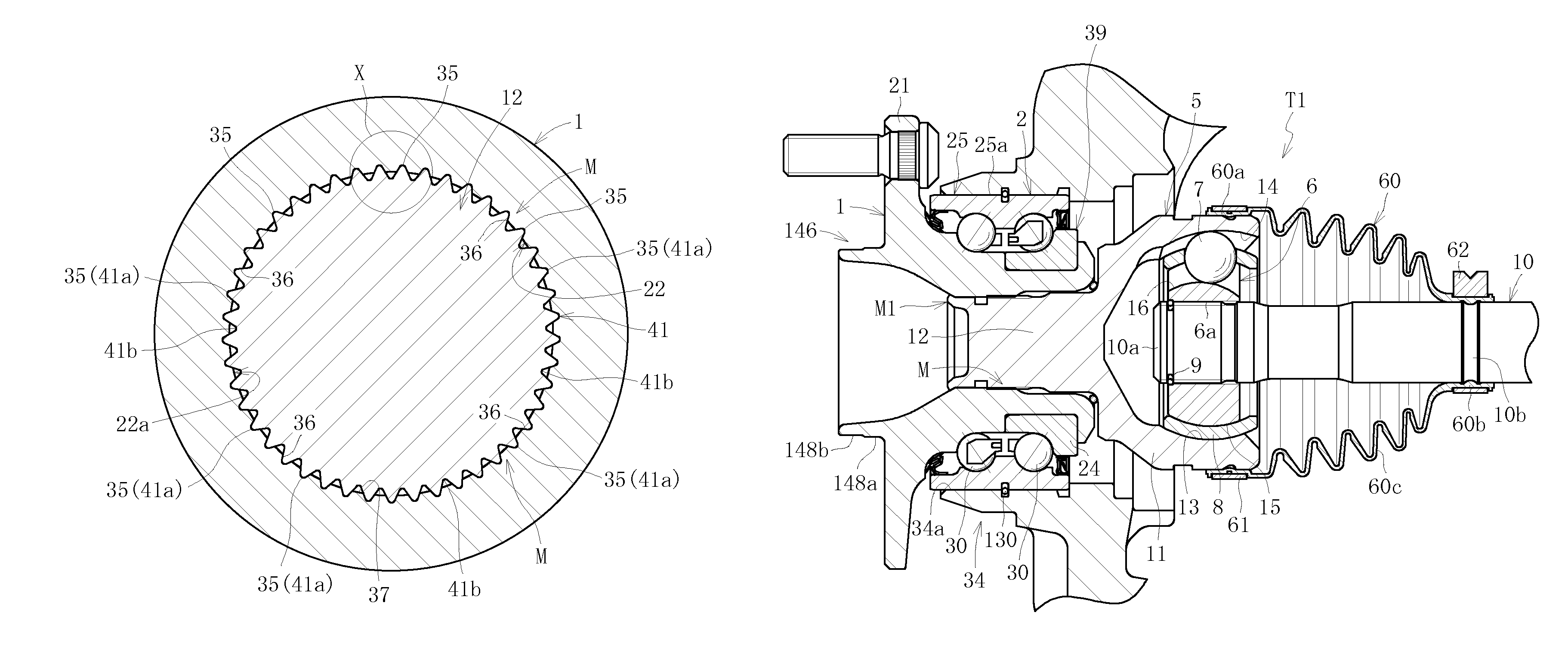
[0191]FIG. 19 illustrates a The shaft section slip-off preventing structure M1 of the wheel bearing device is configured by an outer collar-like locking piece 76 formed by caulking a part of the shaft section 12 to project in the outer diameter direction. In this case, in the hole 22 of the hub wheel 1, the stepped surface 22e is provided between the fitting hole 22a and the tapered hole 22b. The outer collar-like locking piece 76 locks to the stepped surface 22e.

[0192]In the shaft section slip-off preventing structure M1, a jig 67 illustrated in FIG. 20 is used. The jig 67 includes a cylindrical member 78. An outer diameter D5 of the cylindrical member 78 is set to be larger than an outer diameter D7 of the end of the shaft section 12 and an inner diameter D6 of the cylindrical member 78 is set to be smaller than the outer diameter D7 of the end of the shaft section 12.

[0193]Therefore, if axes of the jig 67 and the shaft section 12 of the outer race 5 are aligned and load is appl...
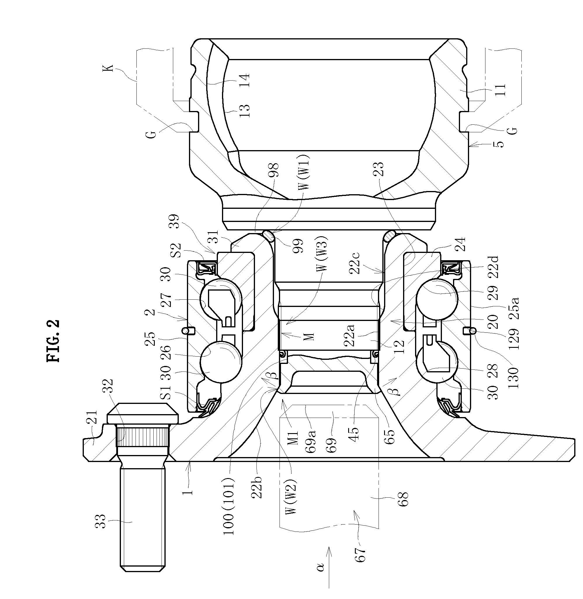
seventh embodiment

[0200]In the wheel bearing device according to the present invention, as illustrated in FIG. 26 illustrating a seventh embodiment, the shaft section slip-off preventing structure M1 does not have to be provided. In this case, as illustrated in FIG. 27, in the circumferential groove 101, a side surface 101a on the spline 41 side is a plane orthogonal to the axial direction and a side surface 101b on an opposite spline side is a tapered surface that is expanded in diameter from a groove bottom 101c to the opposite spline side. A disc-like collar section 102 for centering is provided further on the opposite spline side than the side surface 101b of the circumferential groove 101. An outer diameter dimension D4a of the collar section 102 is set to be the same as or slightly smaller than the hole diameter of the fitting hole 22a of the hole 22. In this case, a very small gap t is provided between an outer diameter surface 102a of the collar section 102 and the inner diameter surface of t...


PUM


Abstract

A recess-projection fitting structure includes projections extending in an axial direction on an outer diameter surface of a shaft section of an outer joint member or an inner diameter surface of a hole of a hub wheel, press-fitting the projections in another of the outer diameter surface and the inner diameter surface along the axial direction, and forming recesses brought into contact and fitted with the projections by press fitting in the other of the outer diameter surface and the inner diameter surface, the projections and the recesses being held in contact with each other through intermediation. An outer member is fitted in a hole of a knuckle of a vehicle. Annular grooves are formed respectively in an outer peripheral surface of the outer member and an inner peripheral surface of the hole of the knuckle, and a snap ring is engaged with both the annular grooves.

Description

BACKGROUND OF THE INVENTION[0001]I. Technical Field[0002]The present invention relates to a wheel bearing device and an axle module for supporting wheels to freely rotate the wheels relative to a vehicle body in a vehicle such as an automobile.[0003]II. Description of the Related Art[0004]Wheel bearing devices have evolved from a structure called first generation in which a double row roller bearing is independently used to second generation in which a vehicle body attachment flange is integrally provided in an outer member. Further, a third generation in which one inner raceway surface of the double row roller bearing is integrally formed with an outer periphery of a hub wheel integrally including a wheel attachment flange has been developed. Further, a fourth generation in which a constant-velocity universal joint is integrated with the hub wheel and the other inner raceway surface of the double row roller bearing is integrally formed with an outer periphery of an outer joint memb...

Claims


Application Information

Patent Timeline
Patent Type & Authority Patents(United States)
IPC IPC(8): F16D1/072
CPCB60B27/00B60B27/0005B60B27/0026B60B27/0042B60B27/0084B60B27/0094B60B35/14B60B35/18F16C19/186F16D1/072F16C35/0635F16C35/067F16D2001/103F16C2226/74F16C19/527F16C2326/02F16D3/223
Inventor YAMAUCHI, KIYOSHIGEOZAWA, MASAHIROUMEKIDA, MITSURU
Owner NTN CORP
Why Eureka
Try Eureka