Rapid thermal firing IR conveyor furnace having high intensity heating section

a conveyor furnace and high-intensity technology, which is applied in the direction of furnaces, domestic stoves or ranges, instruments, etc., can solve the problems of reducing cell efficiency or power output, cell efficiency loss, and contact formation at the expense of cell efficiency loss

Inactive Publication Date: 2013-10-29
TP SOLAR OF USA
View PDF15 Cites 2 Cited by
  • Summary
  • Abstract
  • Description
  • Claims
  • Application Information

AI Technical Summary

Benefits of technology

[0027]The invention is directed to a conveyor or batch-type IR furnace having a plurality of thermal heating zones, including at least one spike zone, in which IR heating elements are backed by ultra high reflectance (on the order of above about 95% IR reflectance) plate type reflector elements, in distinction to the usual block insulation materials. Optionally the lamp elementa may be laterally isolated by placing them in grooves in the high relectance backing element. In still another option, air or inert gas may be directed along the surface of the channels to effect cooling of the lamps.

Problems solved by technology

However, the formation of such contacts is at the expense of a loss in cell efficiency.
The cell efficiency loss arises as a result of electron-hole pairs generated at or near the surface through the absorption of higher energy but short wave length photons.
The defects are traps where electron-hole pairs can recombine thereby reducing cell efficiency or power output.
However, in the current state of the IR furnace art these desiderata are not met.
As a result, the current art suffers from highly inefficient use of the IR lamps that heat the wafers in the various processing zones, and an excess dwell characterized by a broad peak and shallow rate slopes temperature curve in the spike zone.
The dwell peak of current processes is also too long.
The shallow curve / broad peak characteristic process limitation of currently available furnaces has deleterious effects on the metal contacts of the top surface which significantly limits cell efficiency as follows.
First, the frit glass must not flow too much, otherwise the screen-printed contact lines will widen and thereby reduce the effective collection area by blocking more of the cell surface from incident solar radiation.
The result is that the cell looses efficiency due to a short circuit path for the electrons produced.
Since there are dimensional and IR lamp cost constraints, increasing lamp density in the spike zone is not generally a feasible solution.
Increasing lamp density can be significantly counter-productive, in that the increased density easily results in a more gradual slope due to the reflection off the product and the internal surfaces of the spike zone.
Likewise, increasing the power to the lamps is not currently feasible because higher output can result in overheating of the lamp elements, particularly the external quartz tubes.
This results in lower power density, changes in the spectral output of the IR lamp emissions (hence a lower energy output), and results in the need to slow down the conveyor belt speed, thus slowing processing.
Overheating of lamps, e.g., due to thermocouple delay or failure, can cause the lamps to deform, sag and eventually fail.
This deformation also affects uniformity of IR output delivered to the product.
While many metallization furnace operations operate in an air atmosphere, the atmosphere must be relatively controlled and laminar or minimally turbulent, as incoming air can introduce particulates that contaminate the substrate surfaces, and internal turbulence can disturb the product substrate wafers because they are so very thin, light and fragile, being on the order of 150-350 micrometers thick, In addition, at high temperatures, internal turbulence could cause lamp vibration leading to fatigue failure, or inconsistent or reduced output.

Method used


Image

  • Rapid thermal firing IR conveyor furnace having high intensity heating section
  • Rapid thermal firing IR conveyor furnace having high intensity heating section
  • Rapid thermal firing IR conveyor furnace having high intensity heating section

Examples


Embodiment Construction

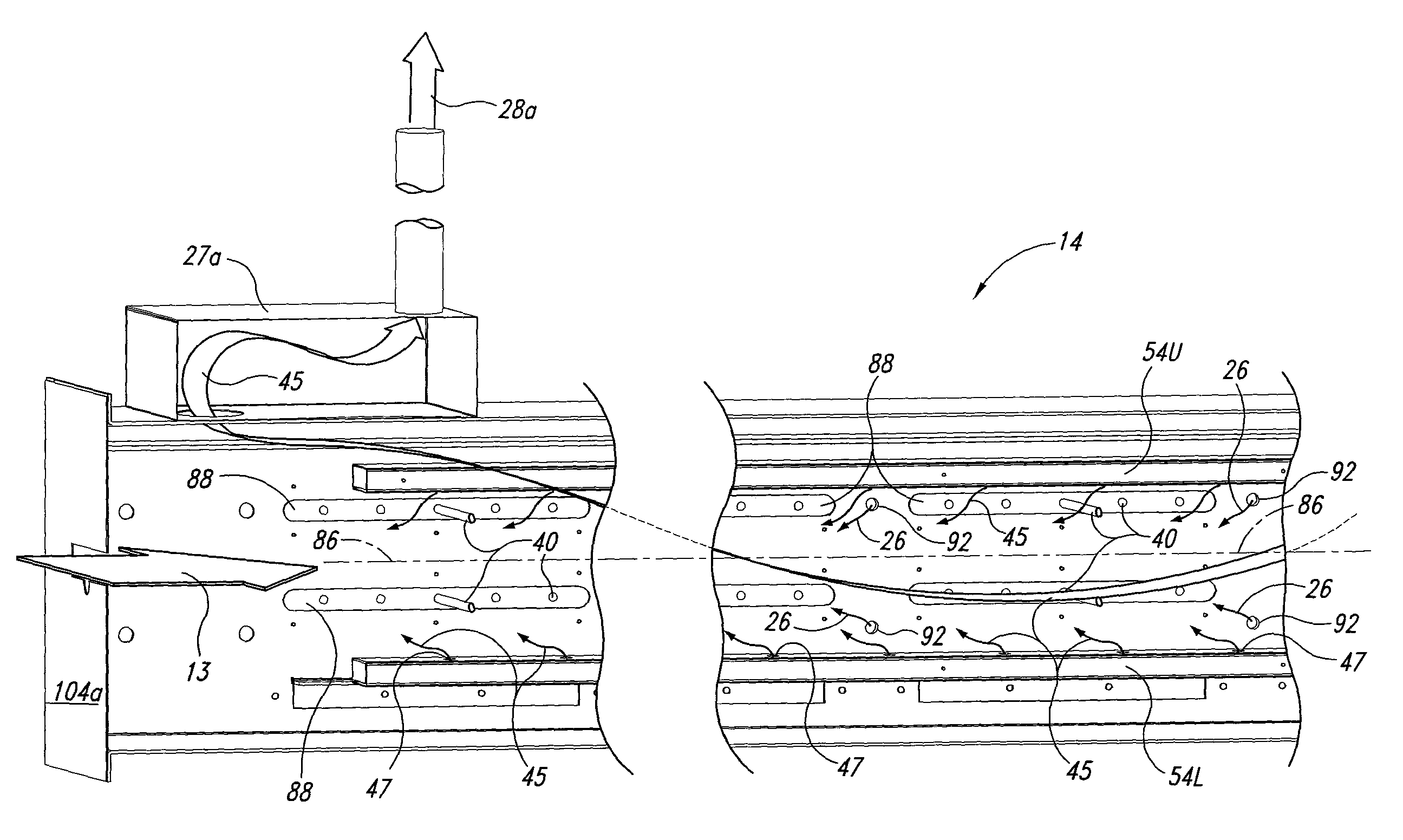
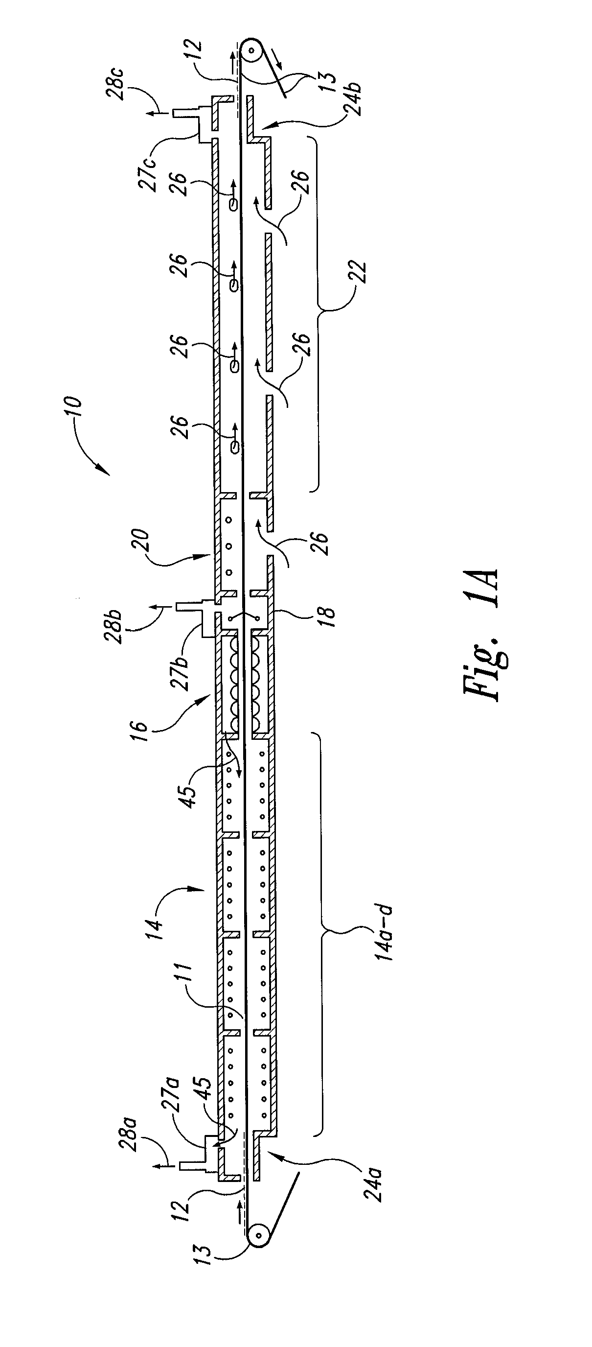
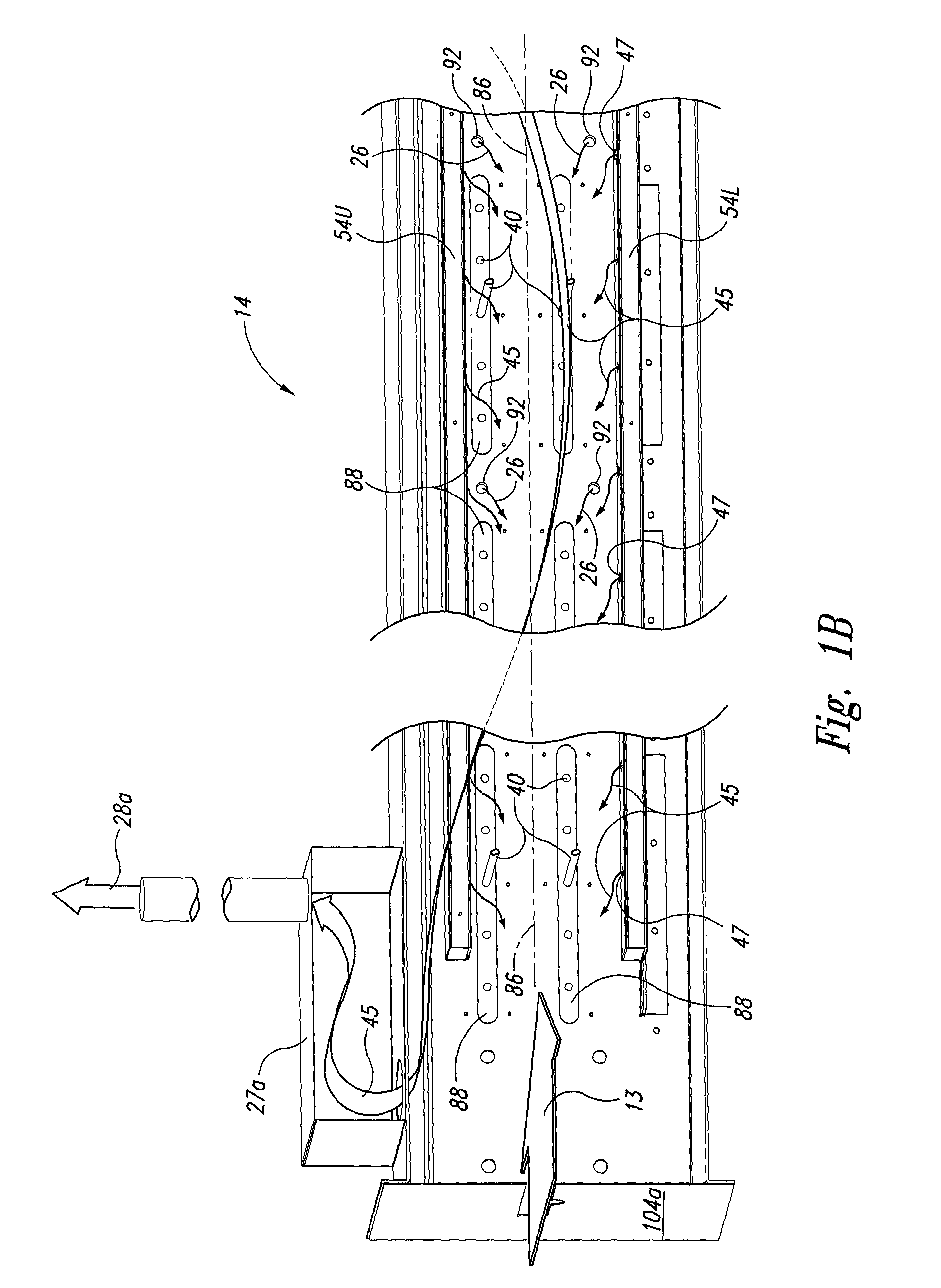
[0060]The following detailed description illustrates the invention by way of example, not by way of limitation of the scope, equivalents or principles of the invention. This description will clearly enable one skilled in the art to make and use the invention, and describes several embodiments, adaptations, variations, alternatives and uses of the invention, including what is presently believed to be the best modes of carrying out the invention.

[0061]In this regard, the invention is illustrated in the several figures, and is of sufficient complexity that the many parts, interrelationships, and sub-combinations thereof simply cannot be fully illustrated in a single patent-type drawing. For clarity and conciseness, several of the drawings show in schematic, or omit, parts that are not essential in that drawing to a description of a particular feature, aspect or principle of the invention being disclosed. For example, the various electrical and pneumatic connections to lights, brakes an...


PUM


Abstract

High reflectance element IR lamp module and method of firing multi-zone IR furnaces for solar cell processing comprising lamps disposed backed by a flat or configured plate of ultra-high reflectance ceramic material. Optionally, the high reflectance plate can be configured with ripples or grooves to isolate each lamp from adjacent lamps in the process zone. Furnace cooling air is exhausted and recycled upstream for energy conservation. Lamp spacing can be varied and power to each lamp individually controlled to provide infinite control of temperature profile in each heating zone. The high reflectance element may be constructed of dense ceramic fiber board, and then coated with high reflectance ceramic composition, and baked or fired to form the finished element.

Description

CROSS-REFERENCE TO RELATED APPLICATIONS[0001]This application is a CIP Application of U.S. Regular application Ser. No. 11 / 768,067 filed Jun. 25, 2007, now U.S. Pat. No. 7,805,064, issued Sep. 28, 2010, entitled Rapid Thermal Firing IR Conveyor Furnace Having High Intensity Heating Section, which in turn is the US Regular Application of U.S. Provisional Application Ser. No. 60 / 805,856, entitled IR Conveyor Furnace Having High Intensity Heating Section for Thermal Processing of Advanced Materials Including Si-Based Solar Cell Wafers, on Jun. 26, 2006, the disclosures of which are hereby incorporated by reference and the priority of which are hereby claimed under 35 US Code Section 119.FIELD[0002]This application is directed to improved IR conveyor furnaces, particularly useful for metallization firing of screen-printed, silicon solar cell wafers, having an improved spike zone and firing processes that result in higher manufacturing throughput and efficiency of the resulting solar cel...

Claims


Application Information

Patent Timeline
Patent Type & Authority Patents(United States)
IPC IPC(8): A45D20/40F26B3/30A21B2/00F26B19/00
CPCH05B3/0076
Inventor RAGAY, PETER G.PARKS, RICHARD W.REY GARCIA, LUIS ALEJANDRO
Owner TP SOLAR OF USA
Why Eureka
Try Eureka