
Minimally invasive skeletal fixation device

a skeletal fixation device, minimally invasive technology, applied in the field of minimally invasive skeletal fixation devices, can solve the problems of joint stiffness, cast/splint application to immobilize adjacent joints, bone fractures, etc., and achieve the effects of small incision size, simple structure and minimal invasiveness

Inactive Publication Date: 2013-11-12
HSU CHIA HAO
View PDF6 Cites 5 Cited by
  • Summary
  • Abstract
  • Description
  • Claims
  • Application Information

AI Technical Summary

Benefits of technology

The device facilitates faster recovery, reduces the risk of wound infection, and enhances the precision and convenience of surgical operations by minimizing incision size and improving the accuracy of hole drilling, thereby reducing the impact of X-ray machine usage on patient and operator health.

Problems solved by technology

When human bodies or animals are hurt in sport injuries or in accidents, bones are often fractured due to being hit by strong external force.
However, when a nonsurgical treatment is used, cast / splint has to be applied to immobilize adjacent joints.
Since it usually takes about two months for fractured bones to heal, the cast / splint immobilization often causes muscle weakness or joint stiffness, which requires rehabilitation to restore normal activity of the patient.
Wound complications such as pain or infection may occur after the surgical operation, and cause increased morbidity of the patient.
However, the conventional tension band wiring technique has the drawbacks of (1) making a large wound by the incision, which require a long period of time to heal and (2) the large wound often causing extensive soft tissue dissection and periosteal stripping and damaging vascular supply of fracture site, which in turn affects the healing of fractured bone.
Further, the large wound is susceptible to easy infection and unnecessary pain, and extension of healing time.

Method used


Image

  • Minimally invasive skeletal fixation device
  • Minimally invasive skeletal fixation device
  • Minimally invasive skeletal fixation device

Examples


first embodiment

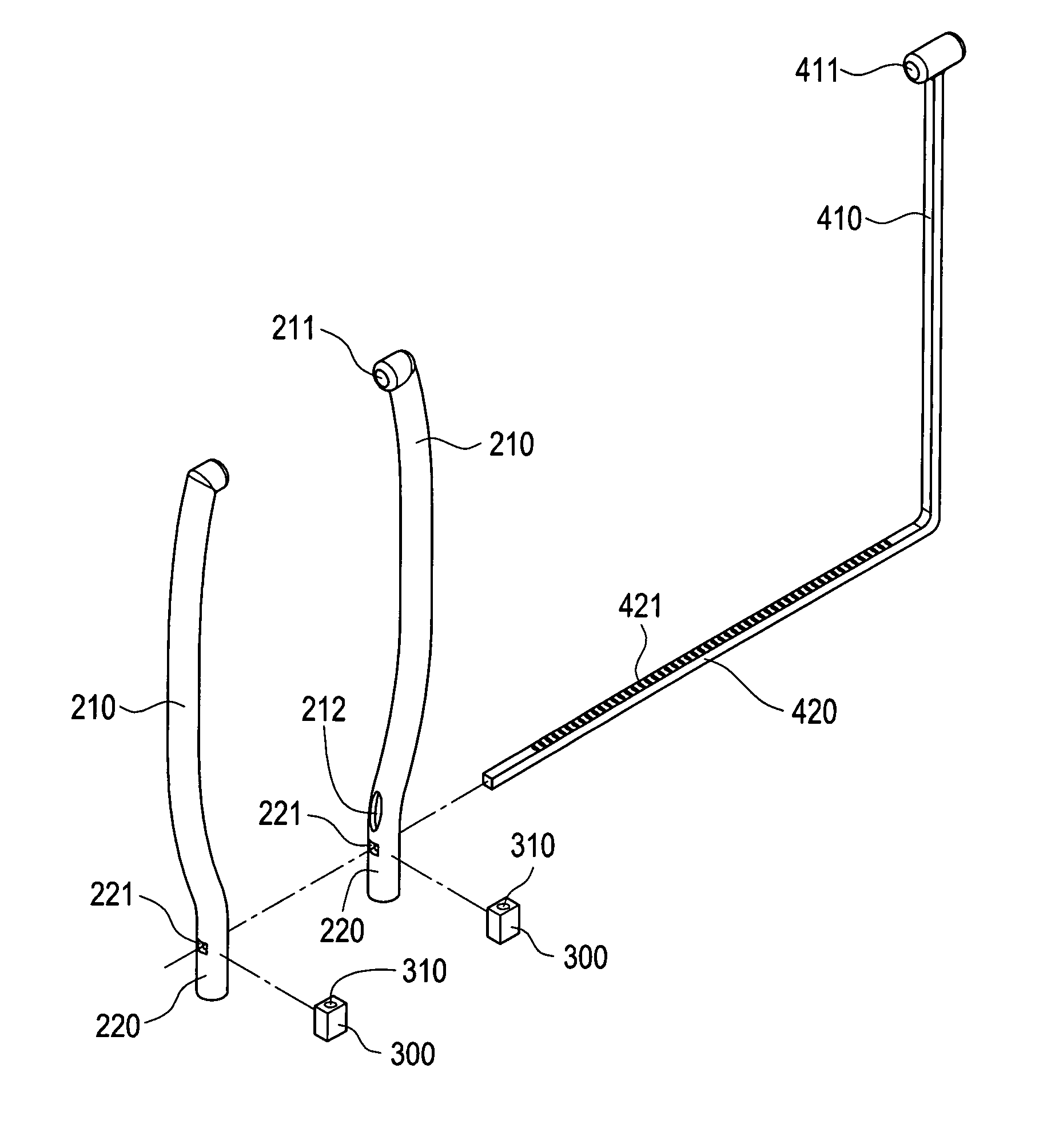
[0019]Referring to FIGS. 2A and 2B, which are respectively a perspective view and an exploded view of a minimally invasive skeletal fixation device constructed in accordance with a first embodiment of the present invention, the minimally invasive skeletal fixation device comprises two arcuate tubes 200 and two positioning members 300 with which an incision made in a surgical operation for treating patella fracture of a patient can be made extremely small for fast recovery so as to allow the patient to return normal movement in a short period.

[0020]Each arcuate tube 200 is in the form of a hook like arcuate tube (which includes an arcuate section and a straight section). Each arcuate tube 200 has a curvature not limited to any specific value. Each arcuate tube 200 comprises a connection section (namely the arcuate section) 210 and a handle section (namely the straight section) 220. Each connection section 210 comprises a hollow tubular portion. The hollow tubular portion extending fr...

second embodiment

[0024]Referring to FIG. 3, which shows an application of a minimally invasive skeletal fixation device in accordance with a second embodiment of the present invention, the minimally invasive skeletal fixation device of the second embodiment is substantially identical to that of the first embodiment and a difference between the two embodiments resides in that in the second embodiment, the positioning members 300 are respectively coupled to the handle sections 220 of the arcuate tubes 200 in a removable manner (for example, the positioning members 300 being coupled to the handle sections 220 of the arcuate tubes 200 with a pivotal joint or a threaded connection), whereby the positioning members 300 allow for adjustment of angles thereof.

[0025]Thus, the minimally invasive skeletal fixation device according to the second embodiment of the present invention allows for flexible adjustment of the installation sites of the K-pins 620. As compared to the known processes of surgical operation...

third embodiment

[0026]Referring to FIG. 4, which shows a perspective view of a minimally invasive skeletal fixation device in accordance with a third embodiment of the present invention, the minimally invasive skeletal fixation device of the third embodiment is substantially identical to that of the first embodiment and a difference between the two embodiments resides in that in the third embodiment, a pad 320 (which comprises a board in the embodiment illustrated, but can be of any other desired shape) is provided between each curved tube 200 and each positioning member 300. With the arrangement of the pad 320 between each arcuate tube 200 and each positioning member 300, the curved tube 200 and the associated positioning member 300 are more surely set at different horizontal planes to facilitate extension of twisting of the wire member 610 around the K-pins 620 for fixation. Particularly, the pad 320 is provided between two arcuate tubes 200. With the arrangement of the pad 320 between two arcuat...


PUM


Abstract

A minimally invasive skeletal fixation device includes two curved tubes and two positioning members. The two curved tubes are attached to each other and are in communication with each other. The positioning members are coupled to the curved tubes. The device is applicable to surgical operations for treating bone fractures and offers the advantages of small incision size, simple structure, easy operation, improved performance of surgical operation, and flexible adjustment of installation sites of Kirschner pins.

Description

FIELD OF THE INVENTION[0001]The present invention relates to a minimally invasive skeletal fixation device, and in particular to a minimally invasive skeletal fixation device having a special assembly comprising two curved tubes and two positioning members, which offers advantages of small incision size, simple structure, and easy operation and is applicable to surgical operations for treating bone fractures.BACKGROUND OF THE INVENTION[0002]When human bodies or animals are hurt in sport injuries or in accidents, bones are often fractured due to being hit by strong external force. Treatment of bone fracture is often carried out through surgical operations or application of cast / splint. However, when a nonsurgical treatment is used, cast / splint has to be applied to immobilize adjacent joints. Since it usually takes about two months for fractured bones to heal, the cast / splint immobilization often causes muscle weakness or joint stiffness, which requires rehabilitation to restore norma...

Claims


Application Information

Patent Timeline
Patent Type & Authority Patents(United States)
IPC IPC(8): A61B17/56A61B17/58A61B17/82A61F2/30
CPCA61B17/1796A61B17/68A61B17/82A61B17/8861A61B17/1767A61B17/1739
Inventor HSU, CHIA-HAO
Owner HSU CHIA HAO
Learn More