Light source device and projector

Active Publication Date: 2013-11-19
SEIKO EPSON CORP
View PDF7 Cites 22 Cited by
  • Summary
  • Abstract
  • Description
  • Claims
  • Application Information

AI Technical Summary

Benefits of technology

[0039]According to the projector of the aspect of the invention, the light source device according to the aspect of the

Problems solved by technology

However, in the light source device in related art, there has been a problem that, for handling of the lights from the plural solid-state light sources, the downstream optical elements (the collection system, an integrator system, etc.) become larger and reduction in size and weight of the light source device becomes difficult.
However, in the case where the fluorescent layer is applied to the light source device including the plural solid-state light sources like the light source device in related art, an excessive thermal load may be applied to

Method used


Image

  • Light source device and projector
  • Light source device and projector
  • Light source device and projector

Examples


embodiment 1

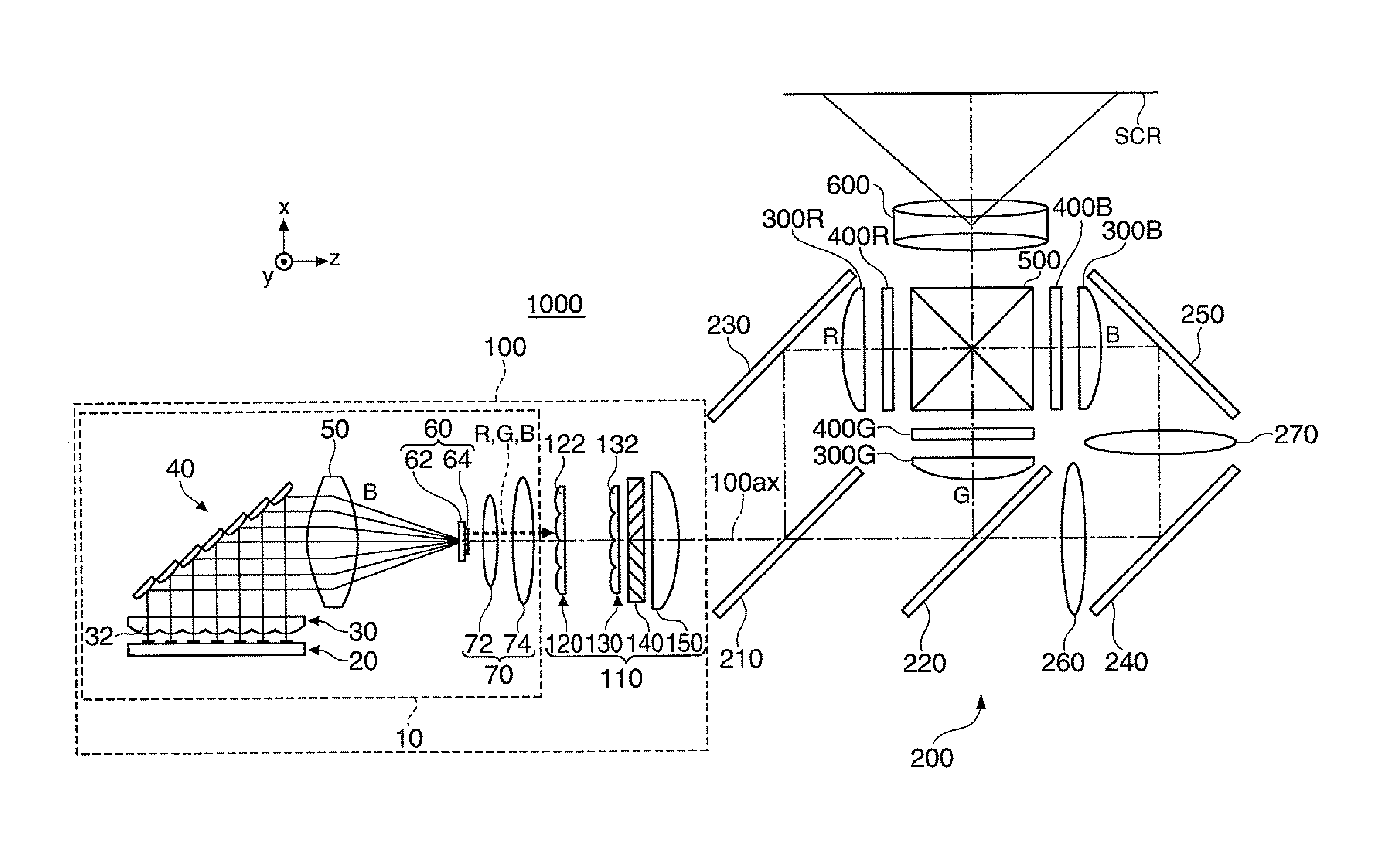
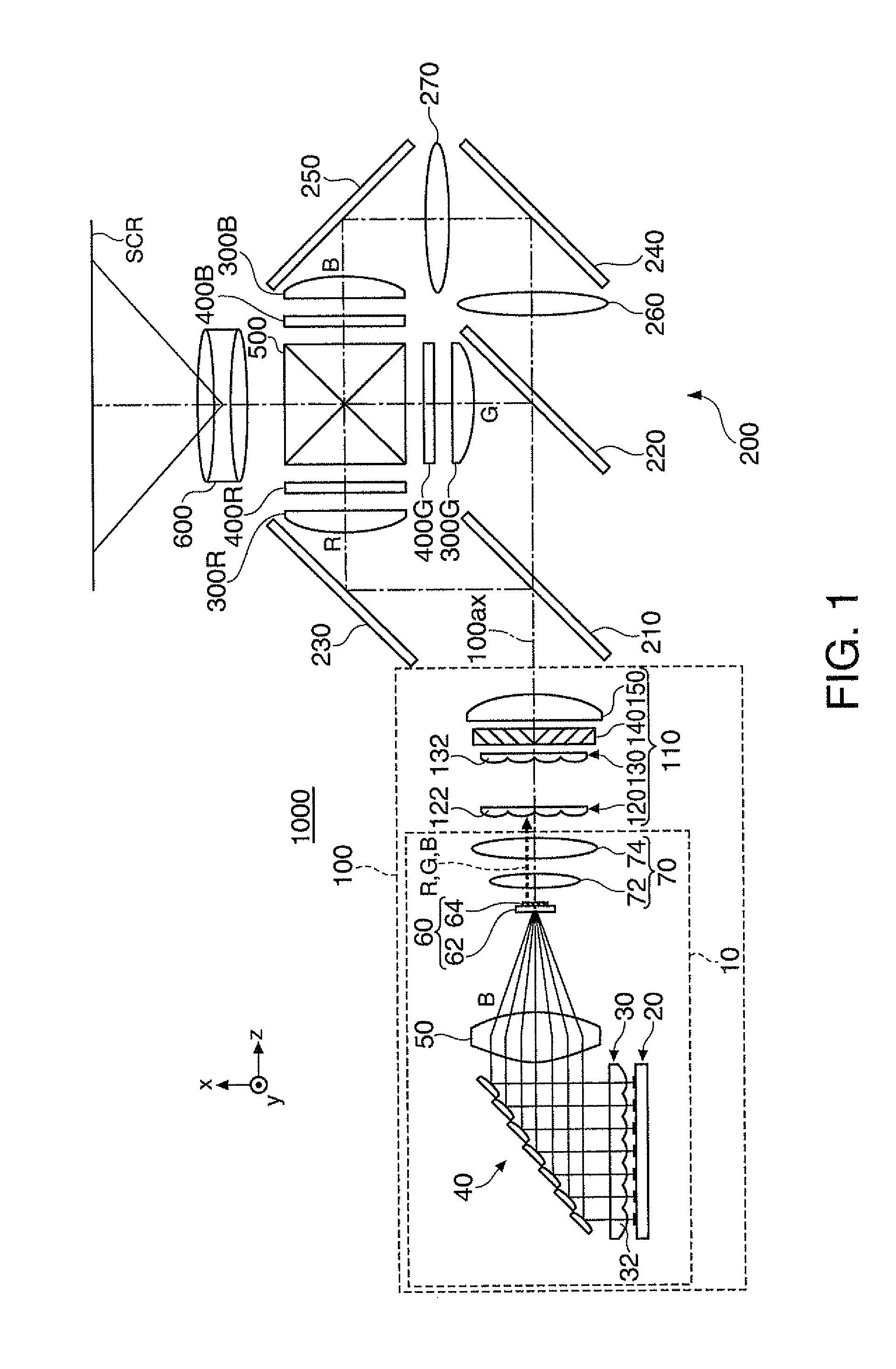
[0051]FIG. 1 is a top view showing an optical system of a projector 1000 according to embodiment 1.

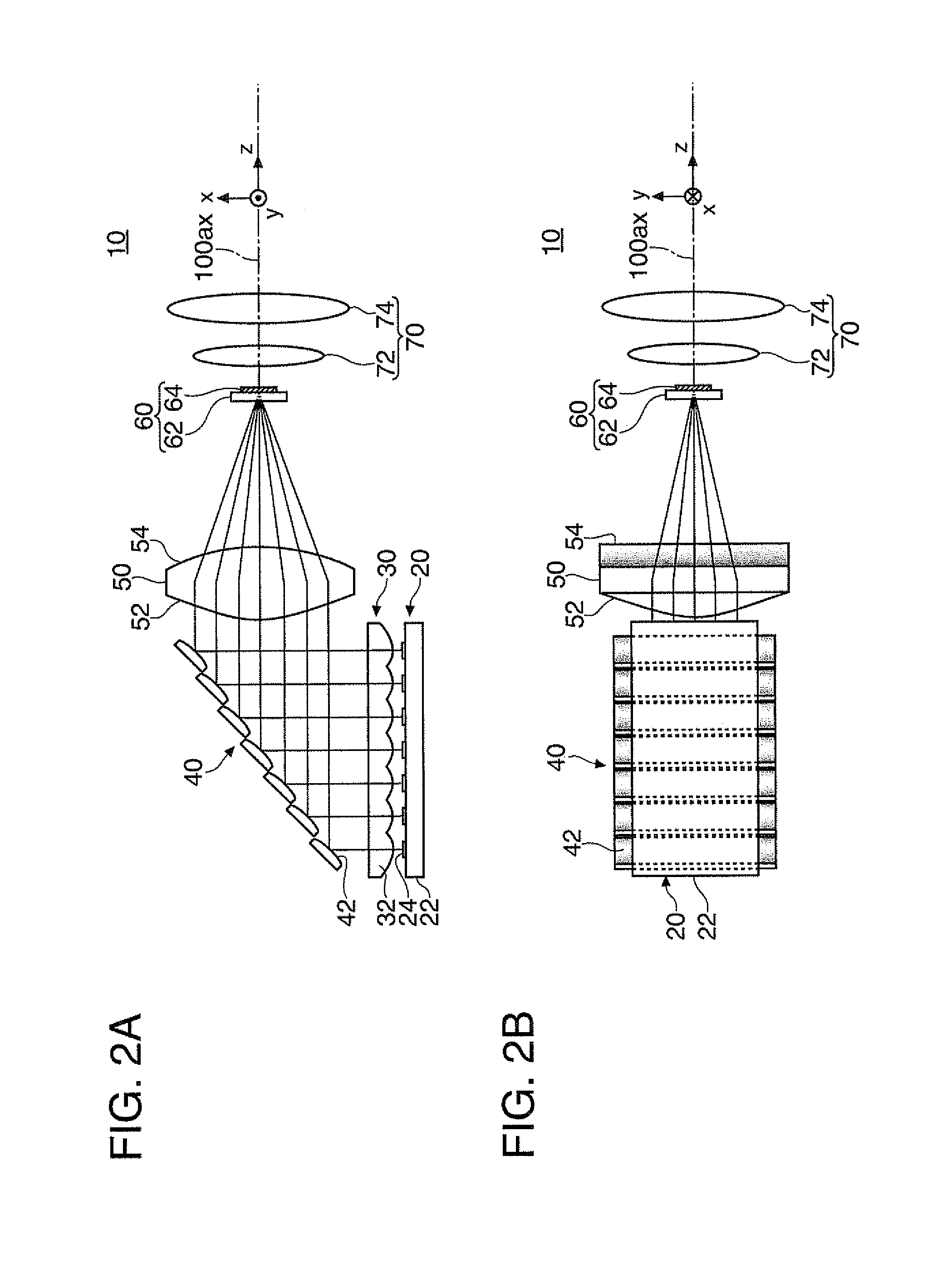
[0052]FIGS. 2A and 2B are diagrams for explanation of a light source device 10 according to embodiment 1. FIG. 2A is a top view of the light source device 10 according to embodiment 1, and FIG. 2B is a side view of the light source device 10 according to embodiment 1.

[0053]FIG. 3 is a diagram for explanation of a solid-state light source array 20 in embodiment 1.

[0054]FIGS. 4A and 4B are graphs showing light emission intensity characteristics of a solid-state light source 24 and light emission intensity characteristics of a fluorescent material in embodiment 1. FIG. 4A is a graph showing the light emission intensity characteristics of the solid-state light source 24, and FIG. 4B is a graph showing the light emission intensity characteristics of the fluorescent material contained in a fluorescent layer 64. The light emission intensity characteristics refer to characteristics as to which...

embodiment 2

[0115]FIGS. 7A to 7D are diagrams for explanation of a light source device 12 according to embodiment 2. FIG. 7A is a top view showing the light source device 12 according to embodiment 2, FIG. 7B is a side view of the light source device 12 according to embodiment 2, FIG. 7C is a graph showing light intensity of blue light entering the fluorescent layer 64, and FIG. 7D shows an in-plane light intensity distribution of the blue light entering the fluorescent layer 64.

[0116]The light source device 12 according to embodiment 2 basically has the similar configuration to that of the light source device 10 according to embodiment 1, however, the reflection surface of the reflection part is different from that of the light source device 10 according to embodiment 1. That is, the light source device 12 according to embodiment 2 has a reflection surface 42a of a reflection part 40a as a flat surface as shown in FIGS. 7A and 7B.

[0117]As described above, in the light source device 12 accordin...

embodiment 3

[0120]FIGS. 8A to 8D are diagrams for explanation of a light source device 14 according to embodiment 3. FIG. 8A is a top view showing the light source device 14 according to embodiment 3, FIG. 8B is a side view of the light source device 14 according to embodiment 3, FIG. 8C is a graph showing light intensity of blue light entering the fluorescent layer 64, and FIG. 8D shows an in-plane light intensity distribution of the blue light entering the fluorescent layer 64.

[0121]The light source device 14 according to embodiment 3 basically has the similar configuration to that of the light source device 10 according to embodiment 1, however, the light-exiting surface of the collection system is different from that of the light source device 10 according to embodiment 1. That is, a light-exiting surface 54a of a collection system 50a comprises a flat surface as shown in FIGS. 8A and 8B.

[0122]As described above, in the light source device 14 according to embodiment 3, the light-exiting sur...


PUM


Abstract

A light source device includes plural solid-state light sources, plural collimator lenses, a collection system, and a fluorescent layer that generates fluorescence from at least a part of the lights from the collection system, wherein at least one anamorphic surface is provided in an optical path from the plural collimator lenses to the fluorescent layer. The plural solid-state light sources are located in positions different from focal positions of the plural collimator lenses in an optical axis direction.

Description

BACKGROUND[0001]1. Technical Field[0002]The present invention relates to a light source device and a projector.[0003]2. Related Art[0004]In related art, a light source device including plural solid-state light sources, plural collimator lenses that respectively nearly parallelize lights from the plural solid-state light sources, and a collection system that collects light from the plural collimator lenses has been known (for example, Patent Document 1 (JP-A-2010-78975)). According to the light source device in related art, the plural solid-state light sources are provided and high-intensity light can be output.[0005]However, in the light source device in related art, there has been a problem that, for handling of the lights from the plural solid-state light sources, the downstream optical elements (the collection system, an integrator system, etc.) become larger and reduction in size and weight of the light source device becomes difficult.[0006]FIG. 9 is a top view showing an optica...

Claims


Application Information

Patent Timeline
IPC IPC(8): G03B21/28F21V9/16G03B21/14
CPCG03B21/2013G03B21/208G03B21/2066G03B21/204
Inventor AKIYAMA, KOICHI
Owner SEIKO EPSON CORP
Why Eureka
Try Eureka