Pressure sensor, differential pressure type flow meter, and flow rate controller

a flow rate controller and differential pressure technology, applied in the direction of valve operating means/release devices, process and machine control, instruments, etc., can solve the problems of deteriorating performance, inability to accurately measure pressure, and growing coagulation, so as to improve the accuracy of flow rate control, improve the accuracy of flow rate measurement, and prevent the generation of scratches on the wafer due to coagulation.

Active Publication Date: 2013-11-26
SURPASS IND
View PDF21 Cites 8 Cited by
  • Summary
  • Abstract
  • Description
  • Claims
  • Application Information

AI Technical Summary

Benefits of technology

[0011]In view of such circumstances, it is an object of the present invention to provide a pressure sensor having a structure in which compressible fluid is prevented from stagnating in the vicinity of a pressure-receiving surface of the pressure sensor in the interior of the pressure introduction portion, and a differential pressure type flow meter and a flow rate controller using this pressure sensor.
[0015]In the pressure sensor as described above, preferably, the pressure introduction flow channel is formed into a bowl shape which narrows the opening area on the side of the inlet port of the fluid, and the inclined surface is provided on the wall surface on the downstream side in terms of the direction of flow of the fluid in the bowl shape, whereby the surface area of the inlet port of the fluid of the pressure introduction flow channel is reduced so that the measurement error due to the dynamic pressure of the fluid can be reduced, and the inclined surface prevents the stagnation of the compressible fluid so that the pressure measurement of the fluid can be performed further accurately.
[0017]According to the differential pressure type flow meter as described above, even though the compressible fluid such as the air is contained in the fluid, the fluid is not stagnated in the pressure introduction channel of the pressure sensors, so that the differential pressure can be detected accurately by the both pressure sensors. Also, since the fluid is not stagnated in the interior of the both pressure sensors and hence a temperature change can be accommodated immediately, the error Caused by a temperature drift of the pressure value due to the temperature change of the fluid can be eliminated. Therefore, the differential pressure type flow meter which performs the flow rate measurement using the both pressure sensors is improved in accuracy in flow rate measurement.
[0019]According to the flow rate controller as described above, since the differential pressure can be detected accurately by the pressure sensors, the accuracy in flow rate measurement by the differential pressure type flow meter is improved. Therefore, the flow rate controller having the flow rate control valve configured to be controlled in opening using the flow rate measured value is able to improve the accuracy in flow rate control.
[0020]According to the present invention as described above, since the compressible fluid such as air contained in the fluid can be prevented from stagnating in the periphery of the pressure detecting unit, the detection values of the pressure sensors become accurate. Also, the inability of measurement or generation of scratches on the wafer due to coagulation of slurry can be prevented and, in addition, when the differential pressure type flow meter is configured, detection is achieved without occurrence of the malfunction even under the temperature change.
[0021]Therefore, remarkable effects such that the flow rate accuracy measured by the differential pressure type flow meter including the pressure sensors as components is improved and, in addition, the flow rate control accuracy of the flow rate controller which performs the opening control of the flow rate control valve using the flow rate measured value measured by the differential pressure type flow meter is improved are achieved.

Problems solved by technology

In the pressure sensor described above, specifically in a case of measuring the pressure of liquid, if compressible fluid such as air or gas is stagnated in the pressure introduction flow channel configured to introduce the fluid to be subjected to the pressure measurement from the primary fluid flow channel, accurate pressure measurement is hardly achieved.
In other words, since stagnation of slurry solution triggers coagulation of the slurry solution, the growing coagulation makes the pressure measurement impossible at last.
Also, in the semiconductor manufacturing process, for example, the coagulated slurry may flow out to cause scratches generated on a wafer.
In addition, the stagnation of the fluid remarkably deteriorates the performance of chemical substitution, and may affect the properties other than the performance of the pressure measurement, such that if pure water is flowed after the chemical solution has flowed, the chemical solution can hardly be flowed off and hence it takes time until the resistance value is lowered.
Still further, as regards the differential pressure type flow meter using the pressure sensor in the related art, the stagnation of the chemical solution cannot react quickly to the effect of temperature change, which may cause a malfunction.
Therefore, the compressible fluid entered the interior of a pressure introduction portion can hardly return to the primary fluid flow channel to be discharged and hence stagnates between the fluid to be subjected to the pressure measurement and the pressure-receiving surface, which may cause various problems on the pressure measurement or the semiconductor process.
In this manner, in a state in which the compressible fluid stagnates on the pressure-receiving surface of the pressure sensor, it is difficult to measure the fluid pressure accurately by the pressure sensor due to the effect of dynamic pressure variations from the fluid flowing in the primary fluid flow channel.

Method used


Image

  • Pressure sensor, differential pressure type flow meter, and flow rate controller
  • Pressure sensor, differential pressure type flow meter, and flow rate controller
  • Pressure sensor, differential pressure type flow meter, and flow rate controller

Examples


first embodiment

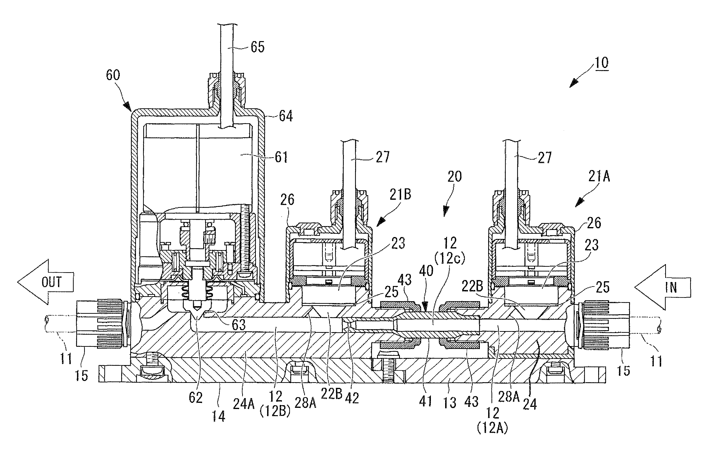
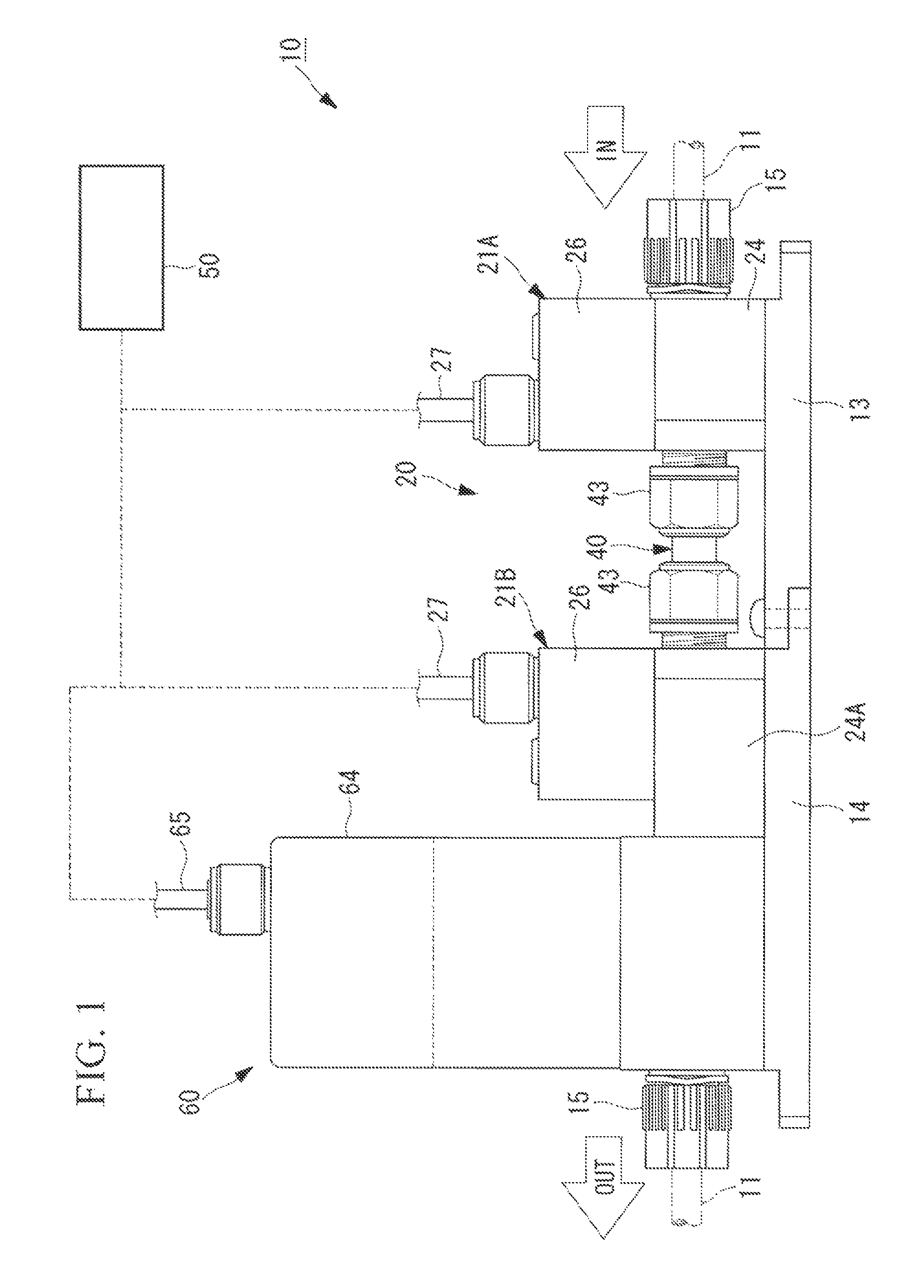
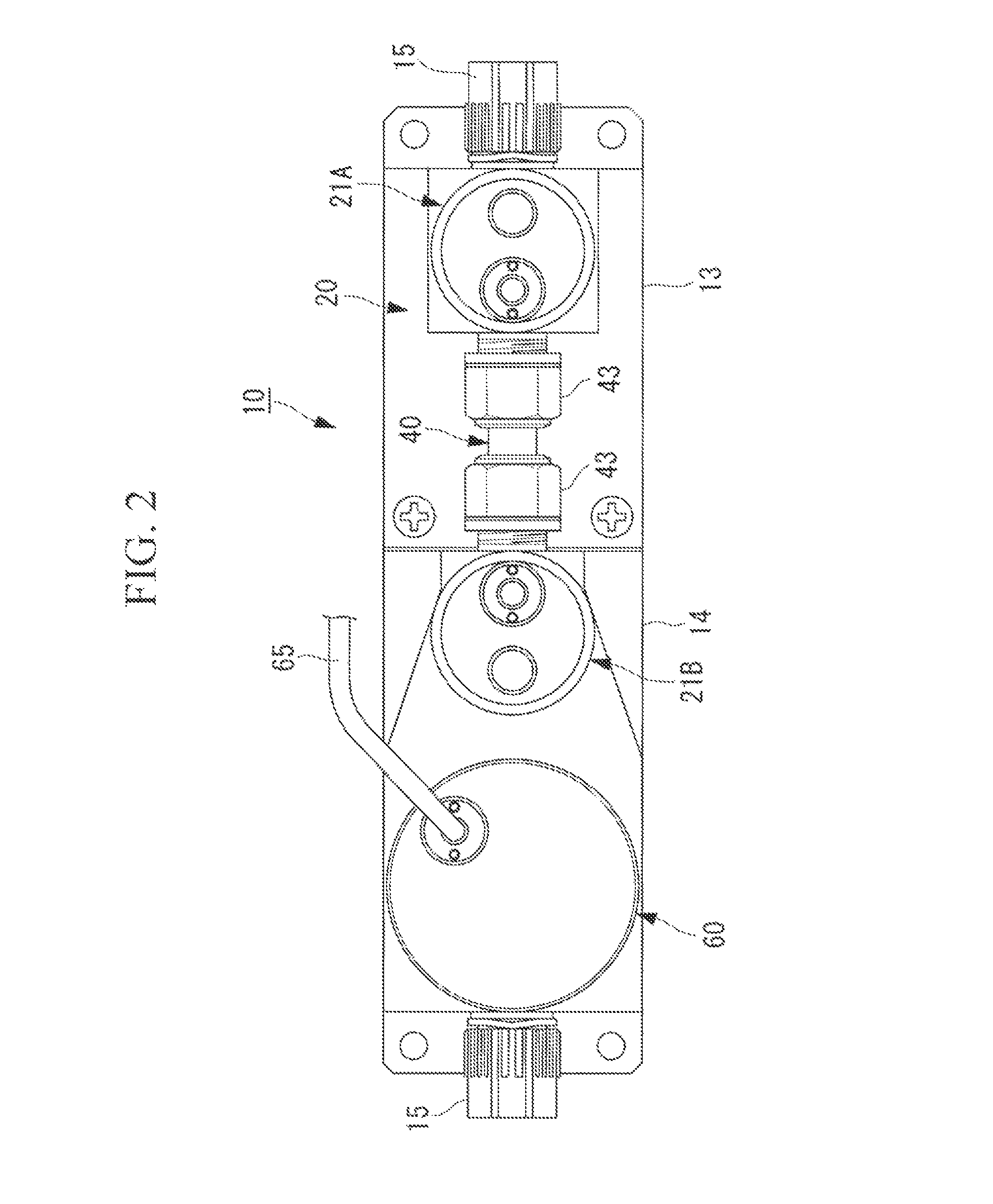
[0042]In the first embodiment shown in FIG. 1 to FIG. 3, FIG. 1 is a front view of a flow rate controller 10, FIG. 2 is a plan view of FIG. 1, and FIG. 3 is a vertical cross-sectional view of FIG. 1. The flow rate controller 10 is a flow rate control apparatus integrated in a pipe 11 which communicates with a primary fluid flow channel 12, described later, and configured to maintain the fluid flow rate of liquid (chemical solution or the like) flowing in the same flow channel constant, and includes a differential pressure type flow meter 20 configured to measure an actual fluid flow rate, and a flow rate adjusting valve 60 configured to be able to control the opening of a valve element. The differential pressure type flow meter 20 is arranged on the upstream side of the flow rate adjusting valve 60 in the direction of flow of the fluid flowing in the primary fluid flow channel 12.

[0043]The differential pressure type flow meter 20 has a configuration in which a pair of pressure senso...

second embodiment

[0069]Even when the configuration described above is employed, the pressure measurement by the first pressure sensor 21A and the second pressure sensor 21B which constitute the differential pressure type flow meter 20 is accurate and stable, whereby the differential pressure obtained by the both pressure sensors 21A, 21B is also stabilized, so that the accuracy or the reliability of the measured flow rate Qf obtained by converting the differential pressure is improved.

[0070]In addition, as regards the flow rate controller 10 which performs the opening control of the flow rate adjusting valve 60 using the measured value of the differential pressure type flow meter 20 described above, when the accuracy or the stability f the measured flow rate Qf is improved, the fluid flow rate control accuracy of the measured flow rate Qf flowing in the primary fluid flow channel 12 is improved.

[0071]In this manner, according to the present invention as described above, since the compressible fluid...


PUM


Abstract

A pressure sensor having a structure in which compressible fluid is prevented from stagnating in the vicinity of a pressure-receiving surface of the pressure sensor in the interior of a pressure introducing portion is provided. In a pressure sensor including a sensor body arranged in a pressure introduction flow channel branched in a T-shape upward from a primary fluid flow channel in which fluid to be subjected to pressure measurement flows, the pressure introduction flow channel includes an inclined surface extending in a direction to increase an opening area on the side of an inlet port of the fluid on a wall surface on the downstream side in terms of the direction of flow of the fluid.

Description

[0001]This application is the U.S. National Stage of International Application No. PCT / JP2008 / 059141, filed May 19, 2008, which designates the U.S., published in Japanese, and claims priority under 35 U.S.C. §§119 or 365(c) to Japanese Application No. 2007-166360, filed Jun. 25, 2007.TECHNICAL FIELD[0002]The present invention relates to a pressure sensor, a differential pressure type flow meter, and a flow rate controller used in a fluid transport piping in various industrial fields such as chemical plants, semiconductor manufacturing, food, or biology.BACKGROUND ART[0003]In the related art, pressure sensors for measuring the pressure of fluid are widely used. The pressure sensors of this type include those used by being installed at a spot where the pressure of fluid containing corrosive chemical agents such as highly-refined nitric acid, hydrochloric acid, and hydrofluoric acid is measured as in a semiconductor manufacturing process, for example. More specifically, in a semiconduc...

Claims


Application Information

Patent Timeline
Patent Type & Authority Patents(United States)
IPC IPC(8): F16K31/12
CPCG01F1/42G05D7/0635Y10T137/2705Y10T137/776Y10T137/7761Y10T137/8326G01F1/34G01L19/00
Inventor IGARASHI, HIROKI
Owner SURPASS IND
Why Eureka
Try Eureka