
Apparatus and method of electronically impregnating a wear-resistant cutting edge

a technology of electronic impregnating and cutting edge, applied in the field of metal treatment, can solve the problems of tearing grass, exposing the lawn to diseases, and general purpose or special purpose knives that are not suitable for extended use before having to be re-sharpening, etc., and achieve the effect of extending the cutting ability and accelerating the wear

Active Publication Date: 2013-11-26
LAMBERT GEORGE H
View PDF27 Cites 10 Cited by
  • Summary
  • Abstract
  • Description
  • Claims
  • Application Information

AI Technical Summary

Benefits of technology

The method provides a durable, wear-resistant cutting edge that reduces the need for frequent sharpening, enhances durability, and is economically simple to apply, suitable for various cutting tools, including knives and lawn mower blades.

Problems solved by technology

For this purpose, knives used for cutting and the like, such as hunting, camping, fishing, kitchen, cutlery, meat or butchering industries and / or general purpose or special purpose knives are generally unsuitable for extended use before having to be re-sharpened to continue its use as a cutting or slicing tool.
Cutting edges found on lawn mower blades are frequently worn quickly causing a tearing of the grass which exposes the lawn to diseases, unless the blades are periodically re-sharpened.
The cutting edge of a blade, such as a knife blade, also has the disadvantage that it wears more rapidly and is damaged more readily, inasmuch as the area of the cutting surface due to abrasion, and wear is markedly reduced owing to the removal of metal by abrasion and also because the cutting surface constitutes a material or finish that is continuously removed.
However, all known devices used to apply carbide or the like deposits are not available to average consumer, or involve such a complicated process that it would not be practical for the average consumer to apply such a cutting edge.

Method used


Image

  • Apparatus and method of electronically impregnating a wear-resistant cutting edge
  • Apparatus and method of electronically impregnating a wear-resistant cutting edge
  • Apparatus and method of electronically impregnating a wear-resistant cutting edge

Examples


Embodiment Construction

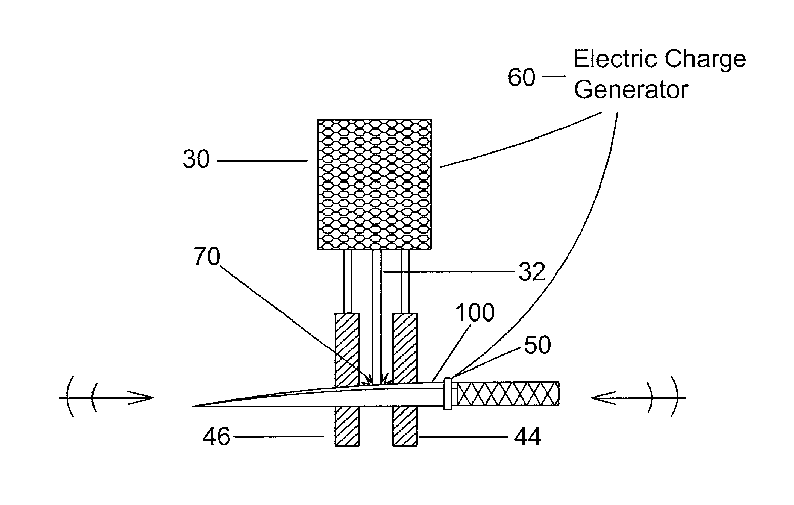
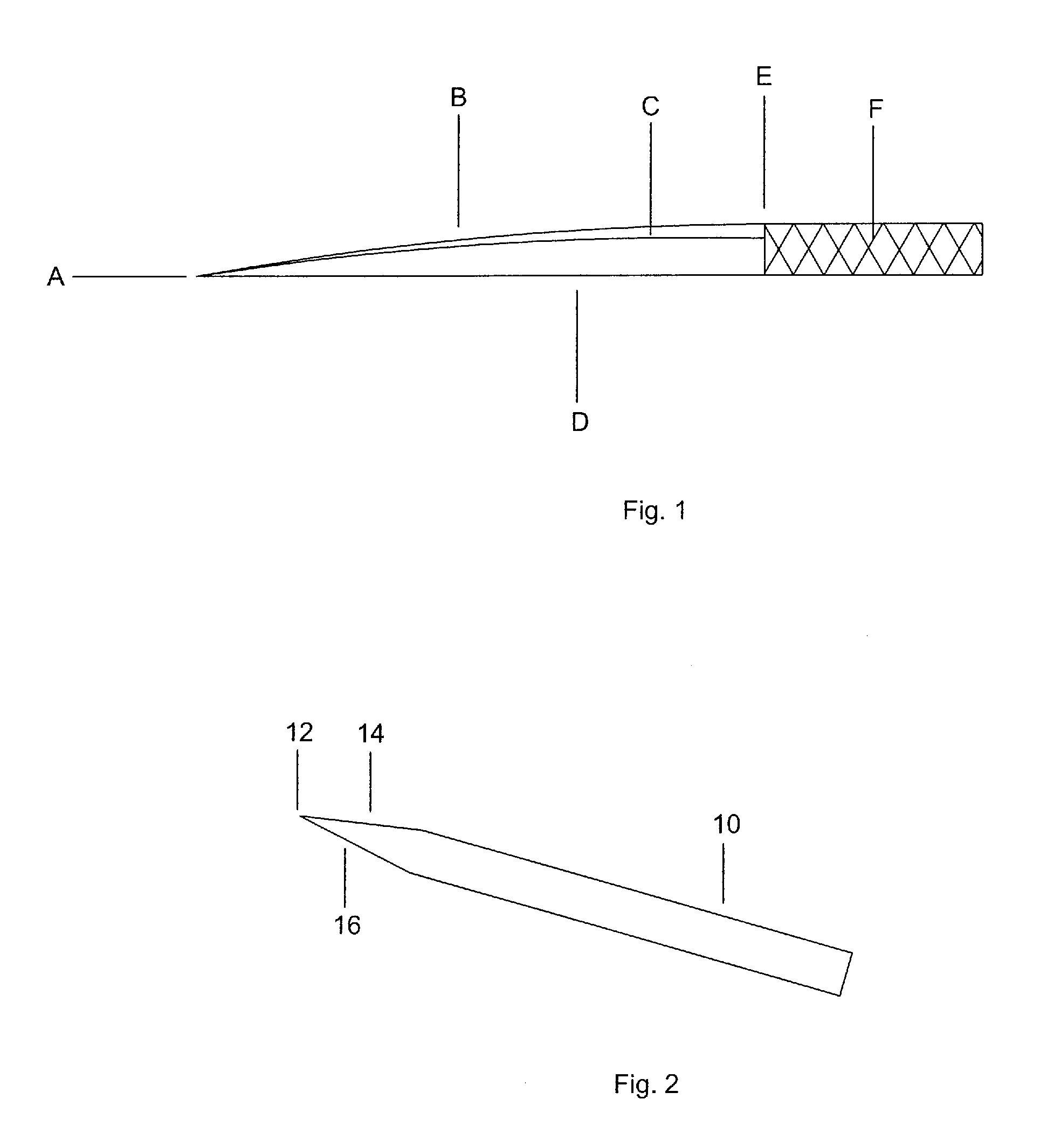
[0040]While the disclosed invention can be used on any type of cutting edge, to simplify the disclosure a knife blade is illustrated. Now referring to FIG. 1, set forth is a pictorial of a knife blade with each edge defined. In particular, the knife blade illustrated is a shank or blade (10) having a point (A). The edge (B) of the blade is defined as the sharpened side that extends from the point to the ricasso (E). The bevel (C) is the sloping area that falls from the spine of the blade towards the edge (B). The bevel (C) is angled from 10-25 degrees. The back (D) of the blade is the opposite side of the edge (B). The ricasso (E) is the flat section of the blade between the tang (F) and the start of the bevel (C) and the tang (F) is the protrusion of the blade in the handle of a conventional knife.

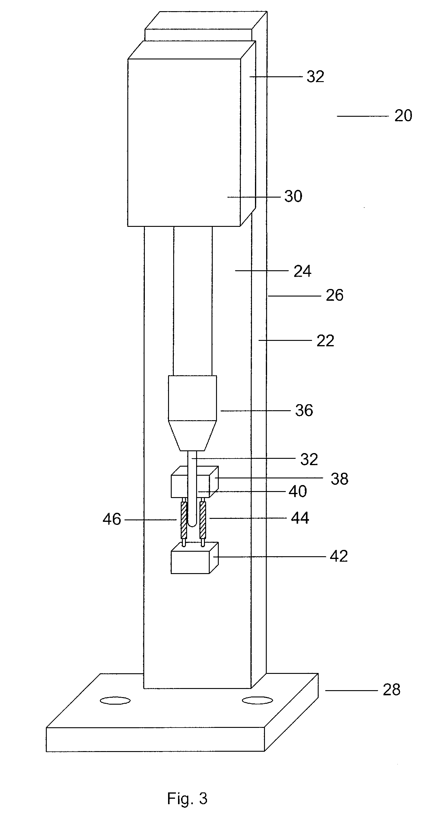
[0041]Referring now to FIG. 2, the instant invention is based upon creating a zone of differential in edge hardness wherein a blade (10) has a cutting edge (12) defined by a first bevel (...


PUM

PropertyMeasurementUnit
angleaaaaaaaaaa
angleaaaaaaaaaa
angleaaaaaaaaaa

Abstract

An apparatus and method for treating a cutting edge with a carbide coating to form a high endurance cutting edge that is self sharpening. The cutting edge has one side of its bevel treated with an electronically impregnated coating to create a wear resistant surface employing Tungsten, Titanium or Vanadium Carbide. The coating providing an abrasion resistant cutting edge and creates a differential hardness on the total cutting edge thereby extending its cutting ability through a wear-resistant surface on its treated face and a faster wear on the untreated surface causing the cutting edge to be self sharpening.

Description

PRIORITY claim[0001]This application is based upon and claims the filing date of U.S. Provisional Patent Application Nos. 61 / 247,666, filed Oct. 1, 2009, and 61 / 247,733, filed Oct. 1, 2009, the contents of which are incorporated herein by reference.FIELD OF THE INVENTION[0002]This invention relates to metal treatment and in particular to an apparatus and method of electronically impregnating a wear-resistant cutting edge for longer endurance and self sharpening of cutting implements.BACKGROUND OF THE INVENTION[0003]It has long been considered desirable to provide a cutting edge which will reduce or minimize the tendency for the edge to wear or abrade off as it is used to cut and slice various substances or medians, thereby minimizing the need to re-sharpen. For this purpose, knives used for cutting and the like, such as hunting, camping, fishing, kitchen, cutlery, meat or butchering industries and / or general purpose or special purpose knives are generally unsuitable for extended use...

Claims


Application Information

Patent Timeline
Patent Type & Authority Patents(United States)
IPC IPC(8): B23K9/04B26B9/00
CPCB23K9/044B23K9/30B23K31/025B26B9/00B23K2201/20B23K2201/34B23K2101/20B23K2101/34
Inventor LAMBERT, GEORGE H.
Owner LAMBERT GEORGE H
Learn More