Optical fibre network

a fiber optic network and optical fiber technology, applied in the field of optical fiber networks, can solve the problems of large amount of remote electronics which must be powered, the clock distribution system calibration, etc., and achieve the effect of reducing the maximum bit ra

Active Publication Date: 2013-12-10
HUAWEI TECH CO LTD
View PDF7 Cites 7 Cited by
  • Summary
  • Abstract
  • Description
  • Claims
  • Application Information

AI Technical Summary

Benefits of technology

[0013]Thus, according to the invention, the propagation delay between the optical modulators and the remote receiver can be determined accurately, even during operation of the network. In this way, the time of transmission of data signals received at the remote receiver can be determined from their time of receipt with very high accuracy. The first and third optical fibers may be housed in the same cable.
[0026]The network may use a separate fiber to provide a continuous wave comb of wavelengths to a remote signal distribution point with the purpose of avoiding limitations from Rayleigh backscatter which would be incurred over a long fiber path if bidirectional working were used.
[0028]Viewed from a further broad aspect, the invention provides an asynchronous real-time Time to Digital Converter (TDC) and data multiplexer employing a local clock and framing signal, for communicating real-time events over a calibrated delay optical communications system. The converter and multiplexer may use statistical multiplexing in order to reduce the maximum bit-rate required.
[0029]Viewed from a further broad aspect, the invention provides a synchronous real-time Time to Digital Converter (TDC) and data multiplexer employing a common reference clock and framing signal for communicating real-time events over a calibrated delay optical communications system. The converter and multiplexer may use statistical multiplexing in order to reduce the maximum bit-rate required.

Problems solved by technology

A major difficulty with this approach is calibrating the clock distribution system to take account of the different propagation delays between the clock source and the detectors.
This leads to a significant amount of remote electronics which must be powered, often in difficult environments (e.g. sub-sea).

Method used


Image

  • Optical fibre network
  • Optical fibre network
  • Optical fibre network

Examples


Embodiment Construction

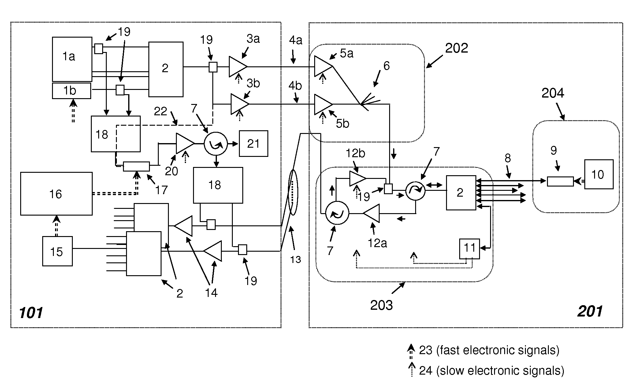
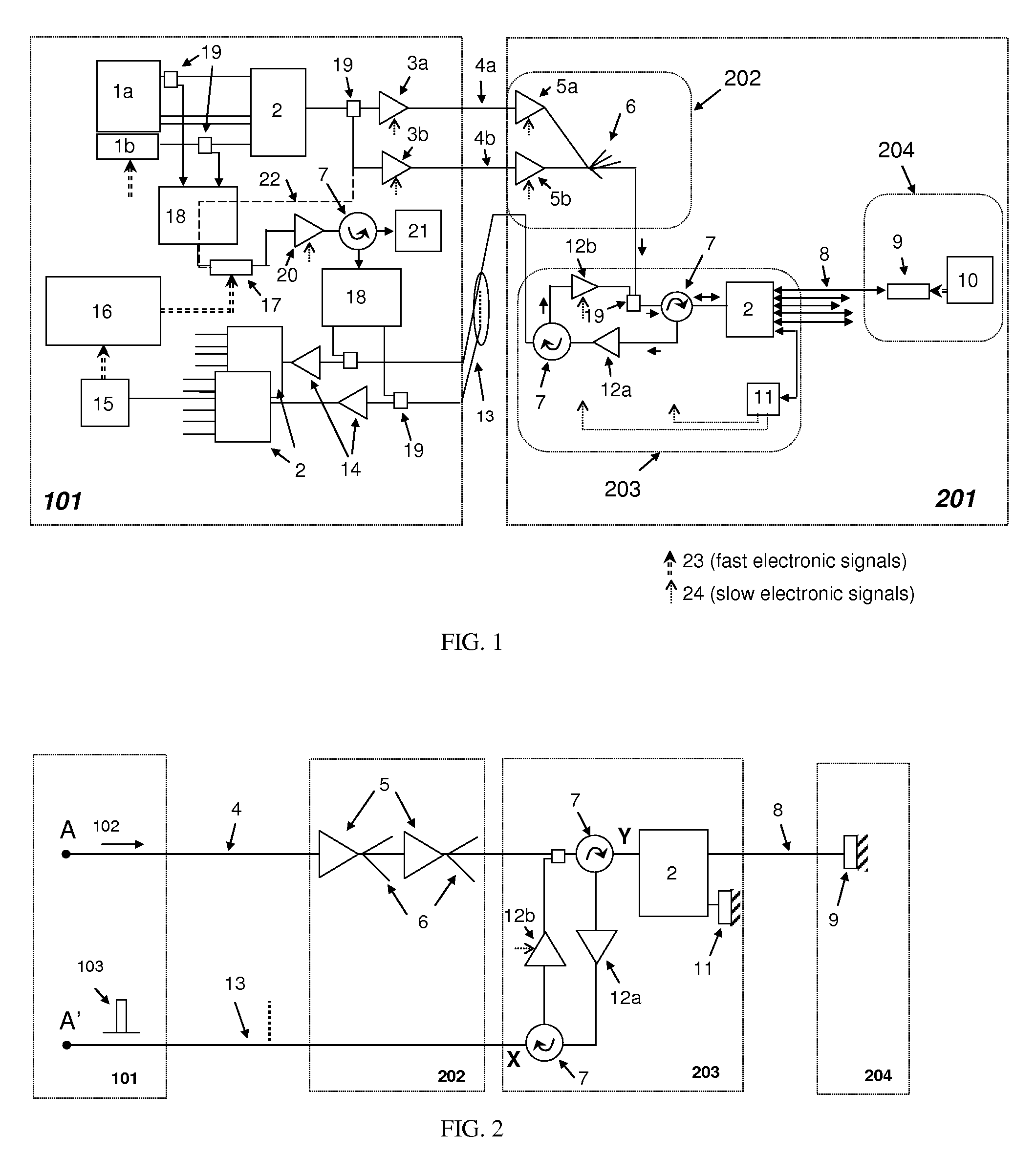
[0037]The invention is based on a type of telecoms WDM-PON (wavelength division multiplexed passive optical network) employing a combination of space, wavelength and time-division multiplexing. The invention overcomes the problems of the prior art by using a novel reflective network architecture which includes a method for calibrating time delays.

[0038]Referring to FIG. 1, light from a centralised array (1a and 1b) of ‘W’ (˜100) individual wavelength optical sources is combined by a multiplexer 2 into a dense WDM (DWDM) signal and amplified by an optical amplifier 3a for transmission over a fiber 4a (and possibly copied by an optical splitter 19 to a second amplifier 3b and fiber 4b for protection) to a remote sensor array 201. At the remote sensor array 201, the signal is amplified by optical amplifiers 5a or 5b and copied by an optical splitter network 6 to ‘S’ (˜100) dense wavelength division multiplexers (DWDMs) 2 via an optical splitter 19 and an optical circulator 7. The DWDM ...


PUM


Abstract

An optical fiber network comprises a laser source (1a) configured to generate laser light of a plurality of wavelengths. A first optical fiber (4a), transmits multi-wavelength light from the laser source to a location remote from the laser source. A wavelength division multiplexer (2) at the remote location (203) is connected to a plurality of second optical fibers (8). A plurality of optical modulators (9) are each connected optically to the wavelength division multiplexer (2) via a respective second optical fiber (8). The wavelength division multiplexer (2) is arranged to de-multiplex the multi-wavelength light received from the first optical fiber (4a) into a plurality of wavelengths and to supply a respective wavelength to each of the second optical fibers (8). The optical modulators (9) are reflective optical modulators each arranged to modulate light received from the associated second optical fiber (8) with a data signal and to reflect the modulated light back along the second optical fiber (8). The wavelength division multiplexer (2) is arranged to multiplex the modulated light from all of the second optical fibers (8) into a wavelength division multiplexed optical signal for onward transmission along a third optical fiber (13).

Description

FIELD OF THE INVENTION[0001]The invention relates to an optical fiber network, and in particular to optical fiber sensor networks, telecommunications networks, computer networks and timing distribution / calibration networks.BACKGROUND TO THE INVENTION[0002]Wavelength division multiplexed passive optical network (WDM-PON) networks for long reach (100 km) telecommunications access networks have been considered by D. B. Payne and R. P. Davey et al. “The Future of Fibre Access Systems”, BT Technol. J. 20.4, p. 104-114 (2002). WDM-PON networks can also be applied to sensor applications. However to collect data in real-time from many distributed sensors it is necessary to reduce uncertainty in event measurement. It is also desirable to minimise the electrical power consumption of the remote equipment.[0003]There is increasing demand for high-speed readout of large capacity remote sensor systems for applications such as neutrino telescopes. These applications frequently require an optical c...

Claims


Application Information

Patent Timeline
Patent Type & Authority Patents(United States)
IPC IPC(8): H04J14/00H04J14/08
CPCH04J3/0682H04J14/0282
Inventor HEALEY, PETERSMITH, DAVID WILLIAM
Owner HUAWEI TECH CO LTD
Why Eureka
Try Eureka