
Hybrid reactor with two reaction zones

a reaction zone and hybrid technology, applied in physical/chemical process catalysts, metal/metal-oxide/metal-hydroxide catalysts, separation processes, etc., can solve the problem of increasing reactor efficiency, not necessarily reducing or avoiding radial in-homogeneity, and reducing the overall rate of chemical conversion. problem, to achieve the effect of increasing the thermal capacity of the reactor, good thermo-capacity and large surface area

Active Publication Date: 2013-12-17
HER MAJESTY THE QUEEN & RIGHT OF CANADA REPRESENTED BY THE MIN OF NATURAL RESOURCES
View PDF3 Cites 3 Cited by
  • Summary
  • Abstract
  • Description
  • Claims
  • Application Information

AI Technical Summary

Benefits of technology

[0008]The invention seeks to provide a hybrid flow reversal catalytic apparatus with improved efficiency, having two different catalyst beds in the reaction zone. A central region of the reaction zone is provided with a low activity catalyst while the peripheral region of the reaction zone (i.e. nearer to the reactor wall) is provided with a high activity catalyst, thereby enabling the reactants to simultaneously react with the high temperature active catalyst and the low temperature active catalyst. Providing the reaction zone with catalysts having different activity levels compensates for the different reaction rates in the central region of the reactor versus the peripheral region of the reactor due to differences in reactor temperature. The invention also seeks to provide method for performing of catalytic and thermochemical processes in said apparatus.
[0013]The invention additionally seeks to provide two different reaction zones. The first reaction zone is the catalyst zone, as described above, in which a heterogeneous reaction takes place. The second reaction zone is provided in beds of porous material, which are positioned above the catalyst zone. Preferably, the porous material is of random packing, structured monolithic or semi-structured form, having porosity in the range between 0.5 and 0.85. More preferably, the porous material is a porous ceramic material. However, other materials that have large surface area and good thermo-capacity may also be used. In the porous ceramic beds, a gas phase homogeneous reaction takes place. Beds of porous material are positioned also before the catalyst beds. Preferably, the porous material is of random packing, structured monolithic or semi-structured form, having porosity in the range between 0.5 and 0.85. These porous ceramic beds themselves assist in the mixing of the chemicals in the reactor. In addition, the ceramic beds are advantageously provided with mixing devices to further assist in the mixing process. The porous ceramic beds also increase the thermal capacity of the reactor in the mixing zone, which is important for the optimal operation of the reactor in the event of fluctuations in concentration of the incoming reactant gases.
[0014]Preferably, the maximum temperature of the reactor is controlled to prevent overheating of the catalyst.

Problems solved by technology

The result of this disparity is a decrease in the overall rate of chemical conversion and increased reactor inefficiently.
However, passing the feed gas mixture through catalyst beds having different catalyst activity sequentially does not necessarily reduce or avoid radial in-homogeneities.
However, increasing the volume of the catalyst bed is undesirable economically because it increases the capital costs and operating costs of the reactor due to the need for more catalyst.
Additionally, when the concentration of the incoming reactant gas varies, an increase in the volume of catalyst is insufficient to reach a conversion rate of over 95%.

Method used


Image

  • Hybrid reactor with two reaction zones
  • Hybrid reactor with two reaction zones
  • Hybrid reactor with two reaction zones

Examples


Embodiment Construction

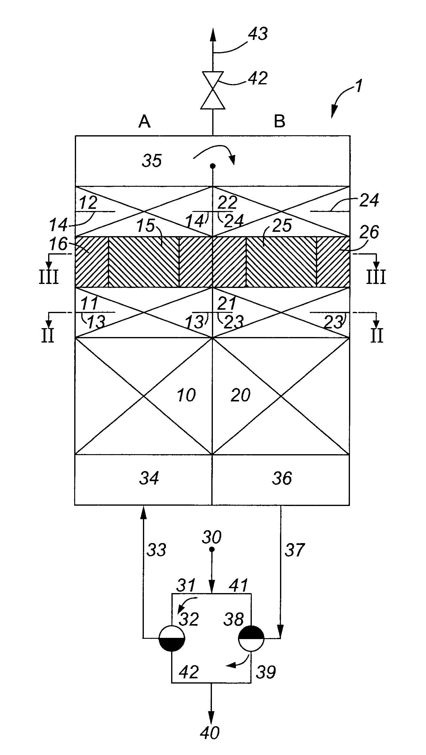
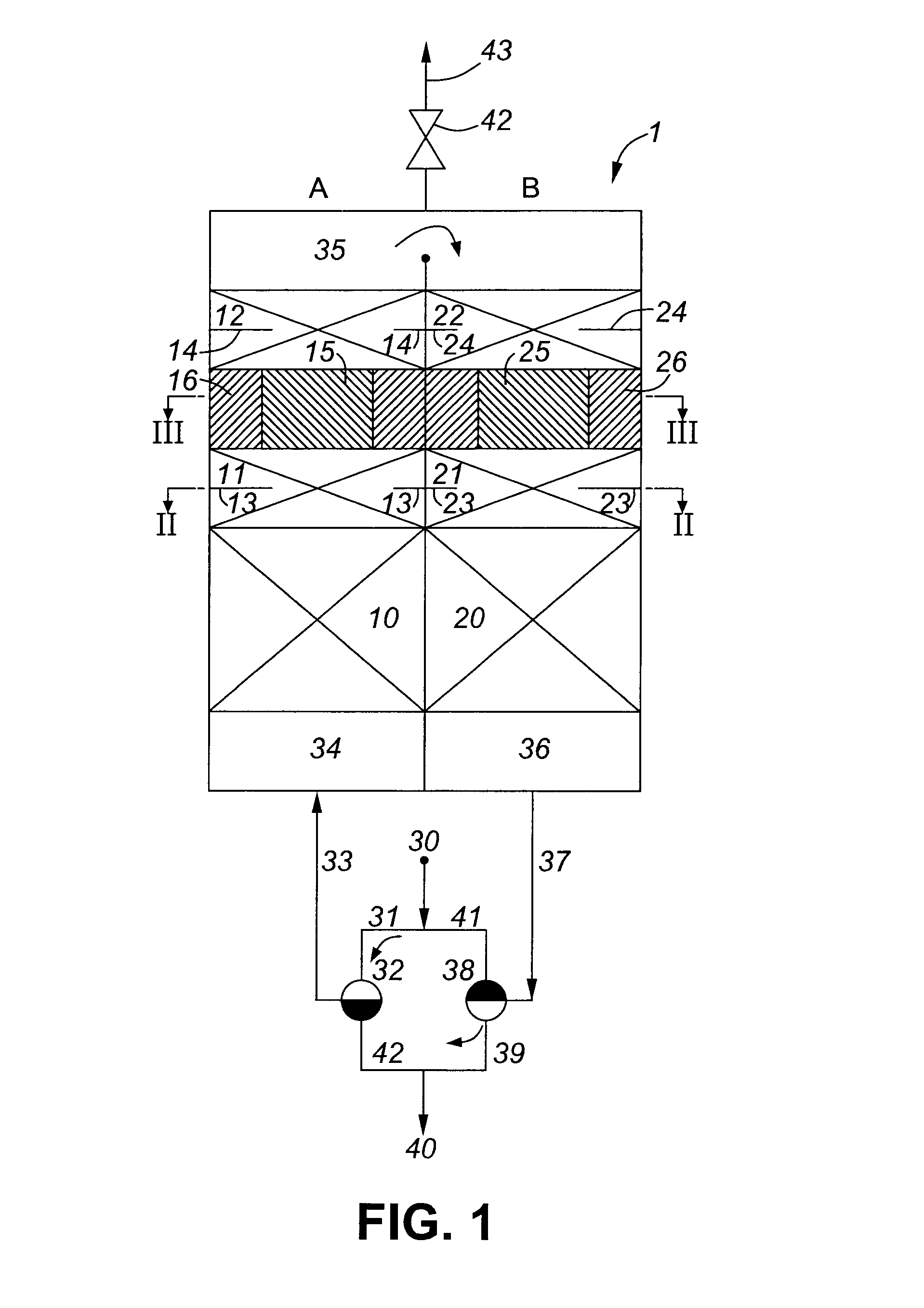
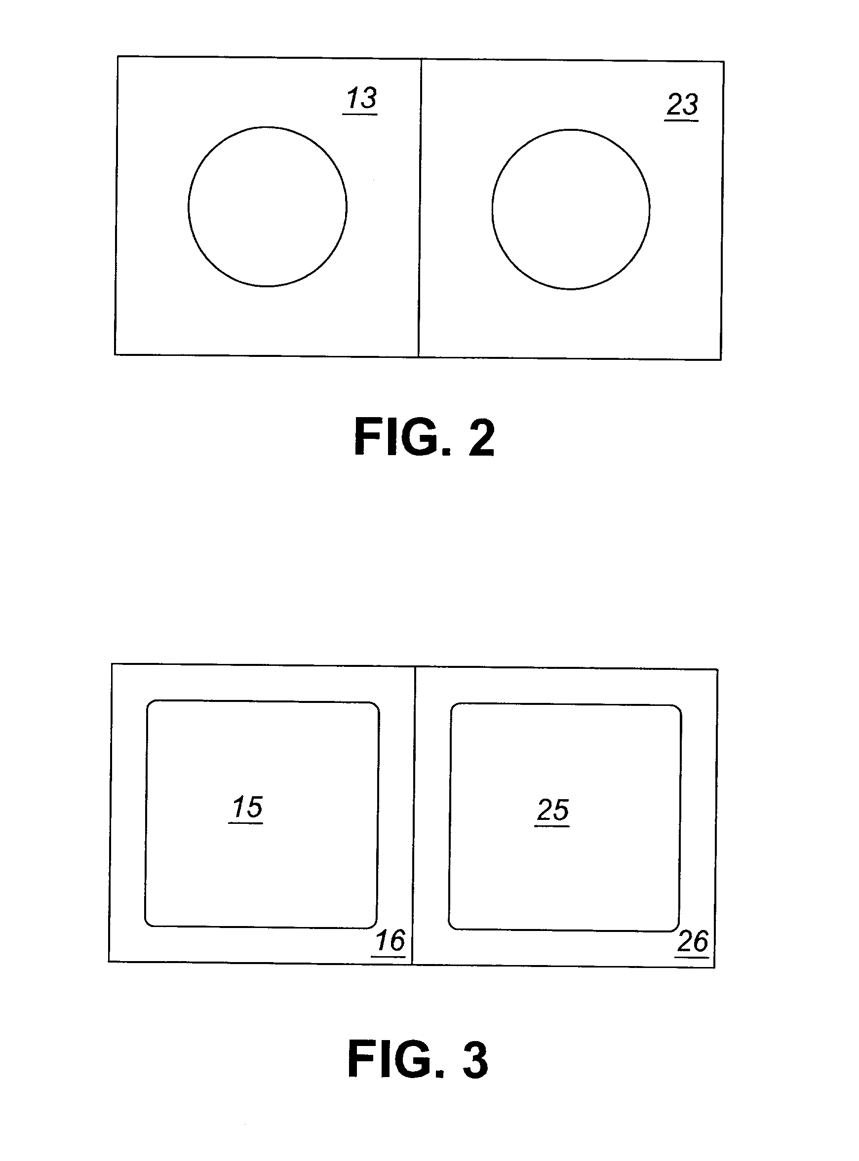
[0031]Referring to FIGS. 1 to 3, a flow reversal reactor (1) having a cylindrical or rectangular cross section is shown having two identical (or mirror-image) sections (A) and (B), which are in fluid connection with each other. Each section has a heat media bed (10) and (20), which is used as a regenerative heat exchanger. The primary function of heat media beds (10) and (20) is to pre-heat the incoming cold reactant gases to the proper temperature, before reaching the reaction zones.

[0032]Sections (A) and (B) each further comprise porous ceramic material beds (11), (12), (21) and (22). The porous ceramic material beds, (12) and (22) provide a region where a gas phase homogenous reaction takes place. The porous ceramic materials beds (11) and (21) provide a region improving gas homogeneities in radial direction. The porous ceramic material beds (11) and (12) incorporate mixing devices (13) and (14) and the porous ceramic material beds (21) and (22) incorporate mixing devices (23) an...


PUM

PropertyMeasurementUnit
temperatureaaaaaaaaaa
temperaturesaaaaaaaaaa
temperatureaaaaaaaaaa

Abstract

The invention relates to a hybrid reverse flow catalytic apparatus having two reaction zones: a homogeneous reaction zone in porous ceramic and a heterogeneous reaction zone with catalyst, arranged in two different catalyst beds. A first catalytic bed located in a central region of the reactor is provided with a low activity catalyst and a second catalyst bed located in a peripheral region of the reactor is provided with a high activity catalyst. The provision of two catalyst beds containing different catalysts reduces the effect of radial temperature gradients in the reactor and improves the overall efficiency of the reactor. The invention also relates to method of performing catalytic and thermochemical reactions in said apparatus.

Description

FIELD OF THE INVENTION[0001]The invention relates to hybrid flow reversal catalytic apparatus having two reaction zones: a homogeneous reaction zone in porous ceramic and a heterogeneous reaction zone with catalyst, arranged in two different catalyst beds. A first catalytic bed located in a central region of the reactor is provided with a low activity catalyst and a second catalyst bed located in a peripheral region of the reactor is provided with a high activity catalyst. The invention also relates to method of performing catalytic and thermochemical reactions in said apparatus. The invention is particularly suited to catalytic gas phase reactions, such as oxidizing ventilation air methane from coal mines or other methane and hydrocarbon emissions from the oil, gas, chemical and petrochemical industries.BACKGROUND OF THE INVENTION[0002]Flow reversal reactors, in which the flow of the reactants and products is periodically reversed, are well known in the field of chemical engineerin...

Claims


Application Information

Patent Timeline
Patent Type & Authority Patents(United States)
IPC IPC(8): B01D53/02
CPCB01J8/0453B01J23/26B01J23/42B01J23/44B01J23/75B01J35/0006B01J35/04B01D53/72B01D53/8668B01D2255/1021B01D2255/1023B01D2255/20746B01D2255/20784B01D2255/402B01D2257/7025B01J2208/00504B01J2208/00522B01J2208/0053B01J2208/0084B01J2208/00884B01J2208/025B01J2219/1923B01J2219/1943Y02C20/20
Inventor SAPOUNDJIEV, HRISTO
Owner HER MAJESTY THE QUEEN & RIGHT OF CANADA REPRESENTED BY THE MIN OF NATURAL RESOURCES
Learn More