Generator, wind turbine, method of assembling a generator and use of a generator in a wind turbine

a technology of wind turbine and generator, which is applied in the direction of electric generator control, machines/engines, mechanical equipment, etc., can solve the problems of limiting the energy conversion efficiency of the turbine, requiring a responsive torque control system, and the electrical generation system is of necessity more complex than that of a constant-speed wind turbine, so as to achieve the effect of reducing size and simplifying configuration

Inactive Publication Date: 2013-12-17
SIEMENS GAMESA RENEWABLE ENERGY AS
View PDF18 Cites 4 Cited by
  • Summary
  • Abstract
  • Description
  • Claims
  • Application Information

AI Technical Summary

Benefits of technology

[0008]It is an object of the present invention to provide a generator that has a simplified configuration, a reduced size, and is in particular suitable for a wind turbine, also a variable-speed wind turbine.
[0012]The favourable use of diode rectifiers allows the replacement of a generator-side converter commonly used in the art. Since said generator-side converter is, as described above, a device that introduces undesirable harmonics while transmitting the generated signal to a utility grid, its replacement by a diode rectifier leads to the elimination of any undesirable harmonics. Furthermore, since the diode rectifier is a particular simple device, and compact the generator of the present invention can be realized in a particularly cost-effective and simple manner.
[0021]A wind turbine generator is traditionally built so that its number of stator poles C and the number of rotor pole shoes M are equal, or such that C is an integer multiple of M, such as 2M, 3M etc. However, with such a physical construction of the generator cogging torque arises when all rotor pole shoes symmetrically pass stator poles at the same time during rotation, and the magnetic attraction is greatest at the moment when the rotor pole and the stator pole are radially aligned. This is a known undesirable effect that contributes to the output ripple, vibration and noise in the machine.
[0022]Therefore, in a preferred embodiment of the invention, the stator coils and the rotor pole shoes are arranged in an asymmetric distribution such that at least a fraction of the rotor pole shoes pass stator coils asynchronously during rotation. This requirement is, for example, automatically given in the above mentioned second alternative of the invention in which the number M of rotor pole shoes is larger than, but not an integer multiple of, the number C of stator coils. In the first alternative of the invention, in which the number C of stator coils is greater than the number M of rotor pole shoes, this may easily be realized—in a similar way as in the second alternative—by choosing the numerical relationship such that the number C of stator coils is not an integer multiple of the number M of rotor pole shoes.
[0023]Since, according to this embodiment of the invention, not all rotor pole shoes symmetrically pass stator poles at the same time during rotation, the magnetic attractions between rotor poles and stator poles are essentially “averaged out” during rotation of the rotor. Therefore, the undesired effect of cogging torque is minimized and vibration and noise in the machine are reduced.
[0030]In another preferred embodiment each of the diode rectifiers comprises at most two diodes. Adding only one or two diodes to each stator coil instead of a rectifier bridge keeps the number of rectifier components to a minimum. This simplified configuration, with a reduced number of elements, allows a further reduction in the overall costs of the generator.

Problems solved by technology

Unfortunately, constant speed operation of a wind turbine limits its energy conversion efficiency due to variable wind conditions.
Such operation, however, requires a responsive torque control system.
Although variable-speed wind turbines are advantageous from the perspective of increased energy conversion and reduced stresses, the electrical generation system is of necessity more complex than that of a constant-speed wind turbine.
Such a solution, due to the fact that the energy generated from the wind turbine needs to pass through various expensive devices, makes the conversion of the generated wind energy unnecessarily expensive.
Further, despite the various levels of signal processing, the generated signal, when ready to be fed into the utility grid, is not free of undesirable harmonic distortion components.
Due to the large number of components, the converter system is very expensive, and these costs have an impact on the cost of the energy fed into the utility grid.
Further, the signal processed in this converter circuit may still not be free of undesirable harmonic distortion components.

Method used


Image

  • Generator, wind turbine, method of assembling a generator and use of a generator in a wind turbine
  • Generator, wind turbine, method of assembling a generator and use of a generator in a wind turbine
  • Generator, wind turbine, method of assembling a generator and use of a generator in a wind turbine

Examples


Embodiment Construction

[0040]In the drawings, like reference numbers refer to like objects throughout. Objects in the diagrams are not necessarily drawn to scale.

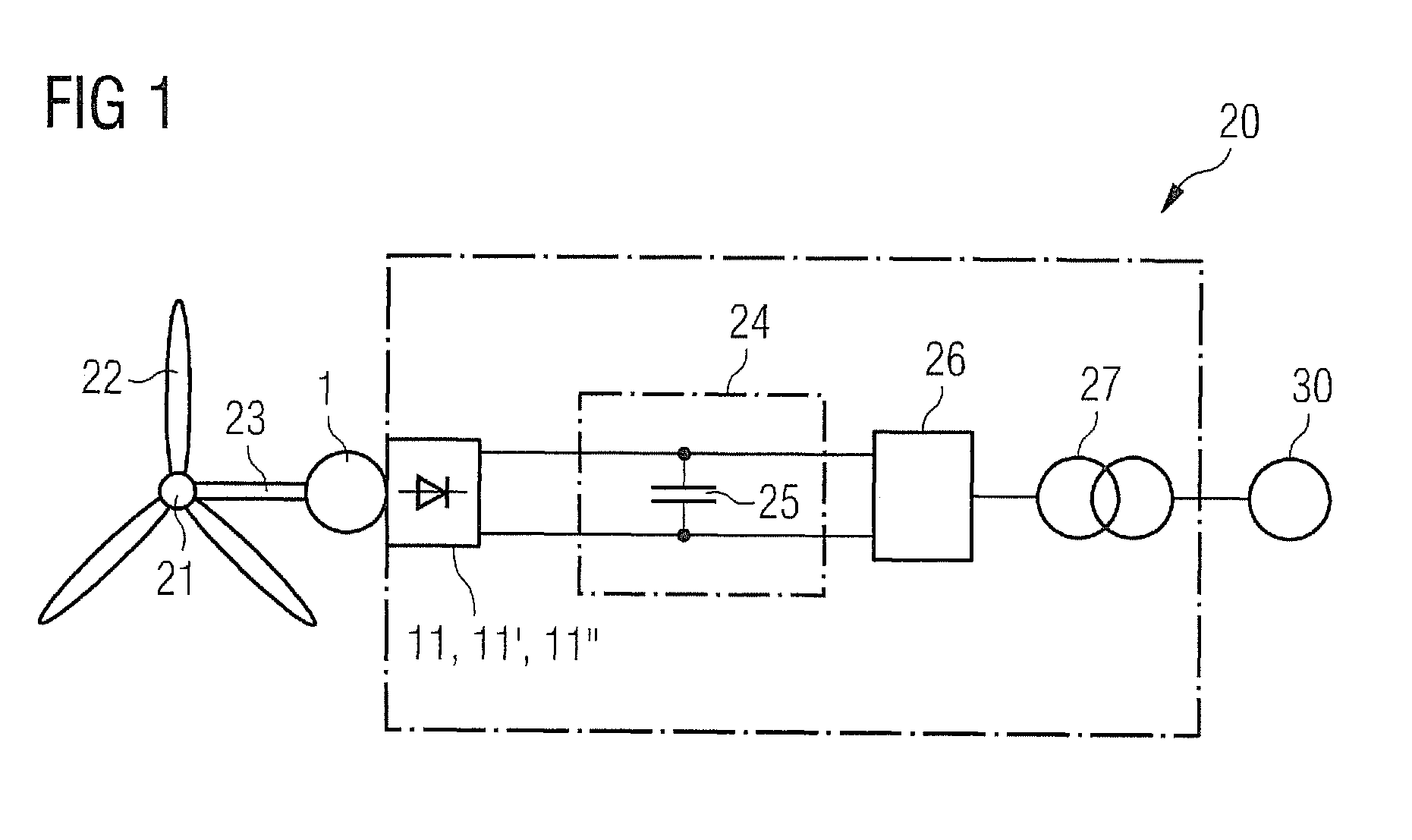
[0041]FIG. 1 schematically shows the principle of construction of the energy producing system of a wind turbine 20. Such a wind turbine 20 usually comprises a tower (not shown in the figure) that may be erected on firm ground, on a seabed, or on any other suitable support. At the top of the tower a Nacelle (not shown in the figure) is mounted which carries a hub 21 with rotor blades 22. As schematically indicated in FIG. 1, a generator 1, which may be a direct-drive generator 1, is arranged in the wind turbine Nacelle and connected to the hub via a shaft 23 or drive train. Generators others than a direct drive generator, for example a generator coupled to the hub via a gearbox, may be conceivable, as it will be readily apparent to a person skilled in the art.

[0042]By rotation of the hub a rotor in a permanent magnet (PM) generator 1 is caused to ...


PUM


Abstract

A generator is provided comprising a rotor with a number of magnetic rotor pole shoes, a stator with a number of stator coils wound on the stator, and a generator-utility grid interface comprising a plurality of diode rectifiers, each diode rectifier is connected to a stator coil and the number of stator coils is greater than the number of rotor pole shoes, or the number M of rotor pole shoes is greater than, but not an integer multiple of, the number of stator coils. A wind turbine utilizing the generator of the present invention and a method of assembling such a generator are provided.

Description

CROSS REFERENCE TO RELATED APPLICATIONS[0001]This application claims priority of European Patent Office application No. 10167615.3 EP filed Jun. 29, 2010, which is incorporated by reference herein in its entirety.FIELD OF INVENTION[0002]The present invention describes an electrical generator, in particular a generator of a wind turbine, and a wind turbine comprising such a generator. The invention further describes a method of assembling such a generator.BACKGROUND OF INVENTION[0003]Wind turbines provide a primary source of energy that can be converted into electricity and supplied to utility power grids, to which the generator is electrically connected. Conversion of wind energy to electrical energy is accomplished in a wind turbine by driving an electrical generator, commonly an AC induction motor. If the electrical power generated by a wind turbine is to be supplied to a utility power grid, then it is required to have a constant frequency that is synchronized to the utility line ...

Claims


Application Information

Patent Timeline
Patent Type & Authority Patents(United States)
IPC IPC(8): H02K11/00H02K11/04
CPCH02K3/28H02K11/046H02K7/1838H02K2213/06H02K2213/12Y02E10/725H02K11/05Y02E10/72H02K21/14H02K2213/03
Inventor STIESDAL, HENRIK
Owner SIEMENS GAMESA RENEWABLE ENERGY AS
Why Eureka
Try Eureka