
Method of and apparatus for controlling a source of light in accordance in a source of sound

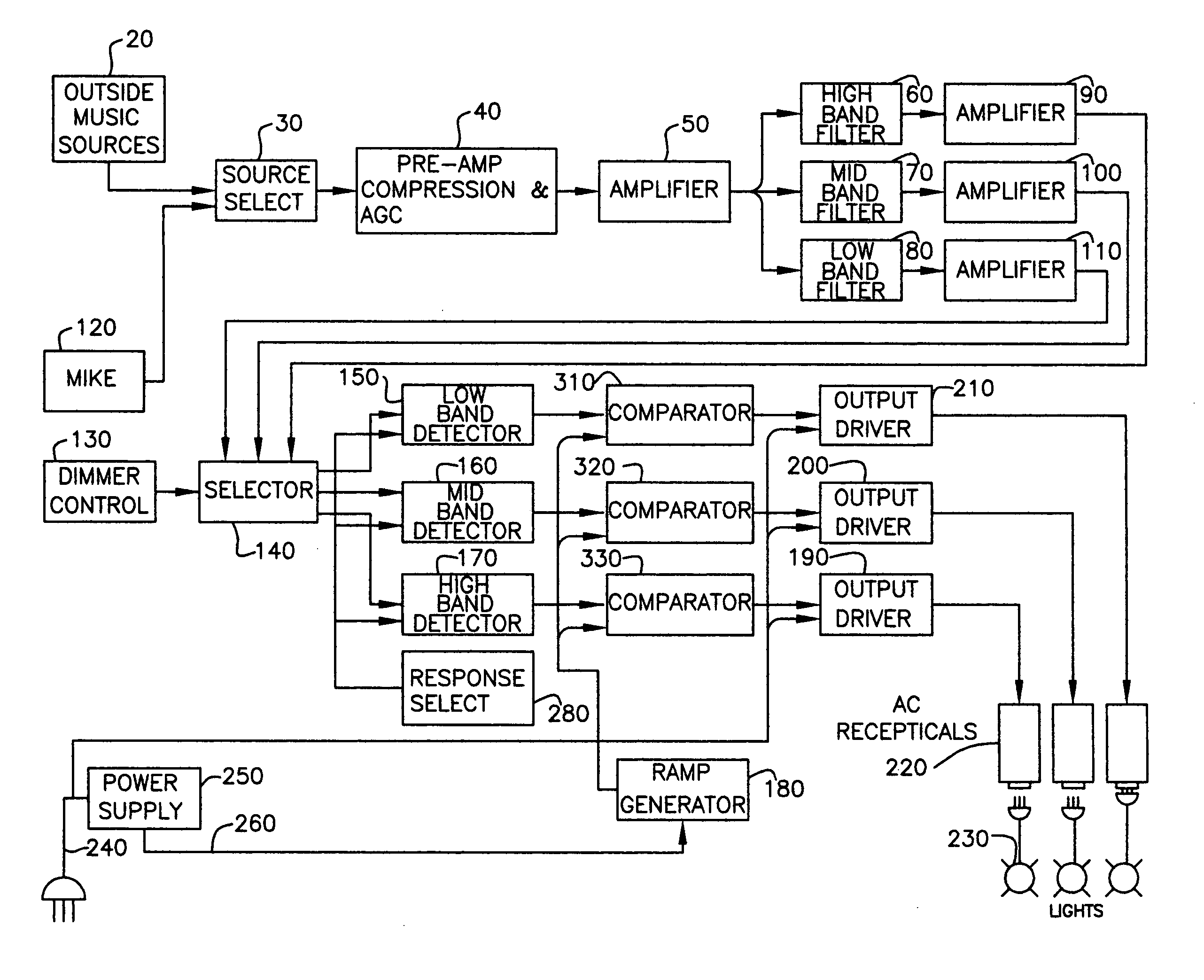
a technology of light and sound, which is applied in the direction of instruments, electrophonic musical instruments, signalling systems, etc., can solve the problems of poor light response to music, poor response of the output voltage to changes in the audio, and poor audio signal response to prior art light control implementations, so as to prevent any light production

Inactive Publication Date: 2013-12-24
WELLS KENNETH A +1
View PDF3 Cites 9 Cited by
  • Summary
  • Abstract
  • Description
  • Claims
  • Application Information

AI Technical Summary

Benefits of technology

The patent text describes an automatic gain control circuit (AGC) used in a compression amplifier. This circuit ensures that the audio and lights are at similar levels for the listener or watcher. It also prevents low-level noise, such as microphone noise or amplifier / resistor noise, from being amplified and producing any output voltage. This prevents any light production due to such low-level noise. Overall, this circuit ensures the optimal level of audio and light output for the audience.

Problems solved by technology

Previous implementations of prior art light control have a very poor response to the audio signal, because of the drastically non-linear designs within the prior art of SCR and Triac firing circuits.
This problem causes a very poor response of the output voltage to changes in the audio.
The combination of these two problems of compression and non-linear firing circuits produce very poor light response to music.

Method used


Image

  • Method of and apparatus for controlling a source of light in accordance in a source of sound
  • Method of and apparatus for controlling a source of light in accordance in a source of sound
  • Method of and apparatus for controlling a source of light in accordance in a source of sound

Examples


embodiment 2

Embodiment 2 differs from the preferred form in the following items:

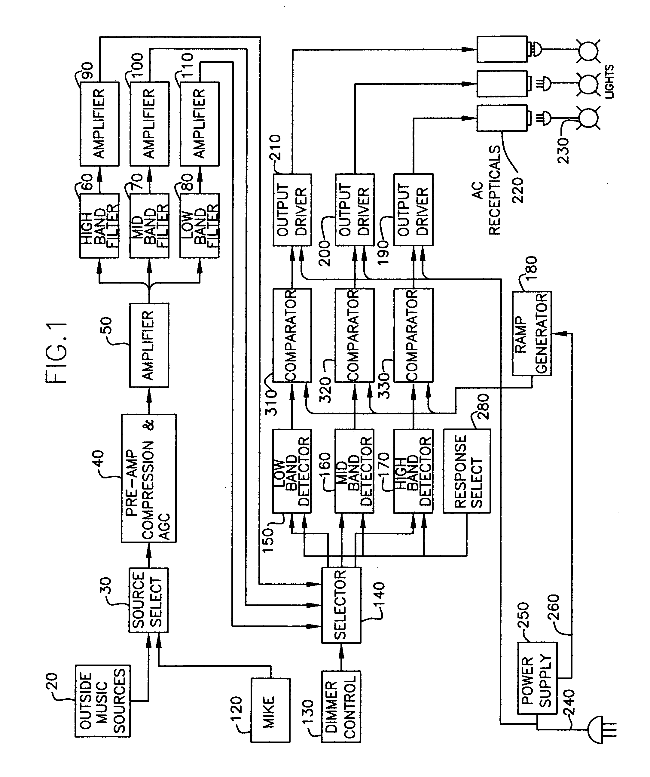
[0055]Item 250 is the power supply and is changed in Embodiment 2 to provide a regulated plus 5 volts, a regulated negative 5 volts and the sync pulse for the ramp generator item 180.

[0056]Item 43, an amplifier (See FIG. 7), is changed from Analog Devices SSM2165-1 to Analog Devices SSM2167-1. Resistor 48 and potentiometer 51 provide a means for the operator to adjust the noise floor, which sets the level at which the background is rejected. Resistor 49 and potentiometer 52 provide a means for the operator to adjust the compression ratio and thus the response of the lights connected to the outputs to the lights to be adjusted for the most pleasing response to the music.

[0057]Items 60, 70 and 120 (See FIG. 5) are three band filters. These filters are changed from a three band filter using operational amplifiers to three switched capacitor filters. The band filters in this embodiment are set with a much sharper cutoff...

embodiment 3

[0060]Item 120, the internal microphone is not included in Embodiment 3.

[0061]Item 30 is changed in embodiment 3 by adding provisions for line input, speaker input, low impedance microphone, or high impedance microphone. There are provisions for the microphone inputs to be fed through; the microphone input connector is directly connected to an output connector. The microphone may be plugged into the unit and be directly connected to an output which can feed an audio amplifier while the signal is tapped off to feed into the inputs of the lighting control. Similarly the speaker right and left signals can be fed in and the out to speakers while the signal is tapped off for an input to the lighting control.

[0062]Item 40 in Embodiment 3 (See FIG. 8), as in Embodiment 2, make use of the special amplifier from Analog Devices, SSM2167. As in Embodiment 2, there is a provision for operator adjustment of the noise floor, the level below which background noise will be rejected. As in Embodimen...

embodiment 4

[0070]Embodiment 4(See FIG. 10A) makes use of transistorized outputs, with pulse width modulation to provide a near unity input power factor instead of using triacs with phase control. Triacs and SCR's, depending on the degree to which they are phased on, have poor input power factor. When used as in the Preferred Form, and Embodiments 2 and 3 the input power factor will vary with the brightness of the lights, items 230, connected to the outlets, items 190, 200, and 210. For higher powers it becomes more important to have a near unity power factor. Pulse width modulation also provides a near linear power output response to the audio signal.

[0071]Item 250, the power supply for the control circuits provides a regulated positive 5 volts and a regulated minus 5 volts as in Embodiments 2 and 3, but it does not provide a sync signal as in the prior embodiments.

[0072]Item 180, the ramp generator is not used in Embodiment 4.

[0073]Item 560 is a triangular wave generator, that provides a tria...


PUM


Abstract

This device, by its organization and operation, processes sound, usually music. It provides output voltages, for driving lights, which is proportionally representative of input sound levels. Range of sound perception of the human ear exceeds the range of perception of the human eye. It is necessary to adjust the sound level by compression and Automatic Gain Control, particularly by compression, to accommodate the eyes.A requirement to have the output drive voltage drive the lights is to have a linear response to the compressed audio signal. This requirement is met with an output drive circuit which, has a linear response to the compressed signal. This is achieved with a linear firing circuit when providing output voltage using SCR's or Triacs. In a straightforward variation of the output circuit to improve the power factor, the linear response is maintained by modulating the output with transistors instead of using SCR's or Triacs.

Description

DIVISIONAL APPLICATION[0001]We claim the benefit of our prior co-pending provision application Ser. No. 60 / 846,964 filed Sep. 26, 2006, entitled TIMBRE LIGHTING CONTROLSBACKGROUND OF THE INVENTION[0002]It is well known to provide an electrical system for producing varying light beams in accordance with music or other audio input. Such systems have converted the music or other audio into electrical signals which are fed into a high frequency filter, an intermediate frequency filer and a low frequency filter. The output of each filter feeds a service such as a light emitting diode or incandescent bulb. See, for example, the following United States patents:[0003]PatentInventorDate1,977,997WallorOctober 19343,228,278WortmanDecember 19663,720,939PolenakMarch 19734,771,280MolinaroSeptember 19885,501,131HataMarch 19883,815,128McClureApril 19743,111,057CramerOctober 1959[0004]Previous implementations of prior art light control have a very poor response to the audio signal, because of the dr...

Claims


Application Information

Patent Timeline
IPC IPC(8): G08B21/00
CPCH05B33/0857H05B37/029H05B45/20H05B47/155
Inventor WELLS, KENNETH AHATCH, VICTOR W
Owner WELLS KENNETH A
Learn More