
Patient selectable joint arthroplasty devices and surgical tools incorporating anatomical relief

a patient-selectable, joint technology, applied in the field of joint replacement and articular resurfacing, can solve the problems of limited repair ability of cartilage, serious physical deformity and debilitation, and uncertain clinical outcomes of biologic replacement materials such as allograft and autograft systems and tissue scaffolds, so as to reduce the amount of bone removed, improve the fit, and improve the effect of natural movement of the join

Active Publication Date: 2014-01-07
CONFORMIS
View PDF553 Cites 181 Cited by
  • Summary
  • Abstract
  • Description
  • Claims
  • Application Information

AI Technical Summary

Benefits of technology

The patent describes a new field of patient-tailored joint implants that address the needs of individual patients. These implants offer better fit, more natural movement, and less invasive surgery compared to traditional one-size-fits-all approaches. The implants can be created from images of the patient's joint, and they can be designed to match existing features in the patient's joint or approximate ideal features. The patent discusses how these patient-adapted or patient-specific implants can be used to treat joint disorders or injuries in a patient-friendly way.

Problems solved by technology

Adult cartilage has a limited ability of repair; thus, damage to cartilage produced by disease, such as rheumatoid and / or osteoarthritis, or trauma can lead to serious physical deformity and debilitation.
However, clinical outcomes with biologic replacement materials such as allograft and autograft systems and tissue scaffolds have been uncertain since most of these materials cannot achieve a morphologic arrangement or structure similar to or identical to that of normal, disease-free human tissue it is intended to replace.
Moreover, the mechanical durability of these biologic replacement materials remains uncertain.
Implantation of these prosthetic devices is usually associated with loss of underlying tissue and bone without recovery of the full function allowed by the original cartilage and, with some devices, serious long-term complications associated with the loss of significant amount of tissue and bone can include infection, osteolysis and also loosening of the implant.
Further, joint arthroplasties are highly invasive and often require surgical resection of the entirety or the majority of the articular surface of one or more bones.
The reaming results in a loss of the patient's bone stock.
Implantation of these prosthetic devices is usually associated with loss of underlying tissue and bone and, with some devices, serious long-term complications associated with the loss of significant amounts of tissue and bone can cause loosening of the implant.
One such complication is osteolysis.
Since the patient's bone stock is limited, the number of possible replacement surgeries is also limited for joint arthroplasty.
As can be appreciated, joint arthroplasties are generally highly invasive procedures and can require surgical resection of the entirety, or a majority of, the articular surface of one or more bones involved in the repair.
Reaming results in a loss of the patient's bone stock and over time subsequent osteolysis will frequently lead to loosening of the prosthesis.
Further, the area where the implant and the bone mate degrades over time requiring the prosthesis to eventually be replaced.
Since the patient's bone stock is limited, the number of possible replacement surgeries can be limited for joint arthroplasty.
In short, over the course of 15 to 20 years, and in some cases even shorter time periods, the patient can run out of therapeutic options ultimately resulting in a painful, non-functional joint.
However, in altering a design to address a particular issue, historical design changes frequently have created one or more additional issues for future designs to address.
Collectively, many of these issues have arisen from one or more differences between a patient's existing joint anatomy and the corresponding features of an implant component.
Moreover, currently available devices do not optimally provide ideal alignment with the articular surfaces and the resultant joint congruity.
Poor alignment and poor joint congruity can, for example, lead to instability of the joint.
In the knee joint, instability typically manifests as a lateral instability of the joint.

Method used


Image

  • Patient selectable joint arthroplasty devices and surgical tools incorporating anatomical relief
  • Patient selectable joint arthroplasty devices and surgical tools incorporating anatomical relief
  • Patient selectable joint arthroplasty devices and surgical tools incorporating anatomical relief

Examples


example 1

Design and Construction of a Three-Dimensional Articular Repair System

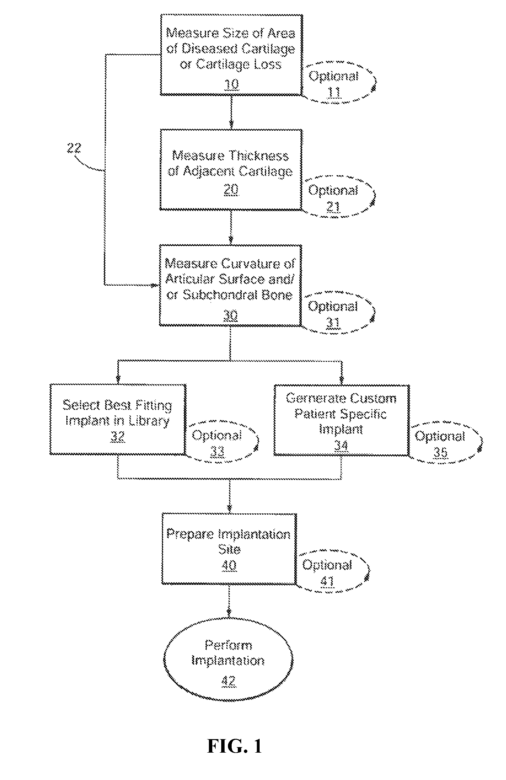
[0622]Areas of cartilage are imaged as described herein to detect areas of cartilage loss and / or diseased cartilage. The margins and shape of the cartilage and subchondral bone adjacent to the diseased areas are determined. The thickness of the cartilage is determined. The size of the articular repair system is determined based on the above measurements. In particular, the repair system is either selected (based on best fit) from a catalogue of existing, pre-made implants with a range of different sizes and curvatures or custom-designed using CAD / CAM technology. The library of existing shapes is typically on the order of about 30 sizes.

[0623]The implant is a chromium cobalt implant. The articular surface is polished and the external dimensions slightly greater than the area of diseased cartilage. The shape is adapted to achieve perfect or near perfect joint congruity utilizing shape information of surrounding cart...

example 2

Minimally Invasive, Arthroscopically Assisted Surgical Technique

[0624]The articular repair systems are inserted using arthroscopic assistance. The device does not require the 15 to 30 cm incision utilized in unicompartmental and total knee arthroplasties. The procedure is performed under regional anesthesia, typically epidural anesthesia. The surgeon can apply a tourniquet on the upper thigh of the patient to restrict the blood flow to the knee during the procedure. The leg is prepped and draped in sterile technique. A stylette is used to create two small 2 mm ports at the anteromedial and the anterolateral aspect of the joint using classical arthroscopic technique. The arthroscope is inserted via the lateral port. The arthroscopic instruments are inserted via the medial port. The cartilage defect is visualized using the arthroscope. A cartilage defect locator device is placed inside the diseased cartilage. The probe has a U-shape, with the first arm touching the center of the area ...

example 3

Design and Construction of a Implant and / or Surgical Tool Incorporating a Negative Anatomical Relief

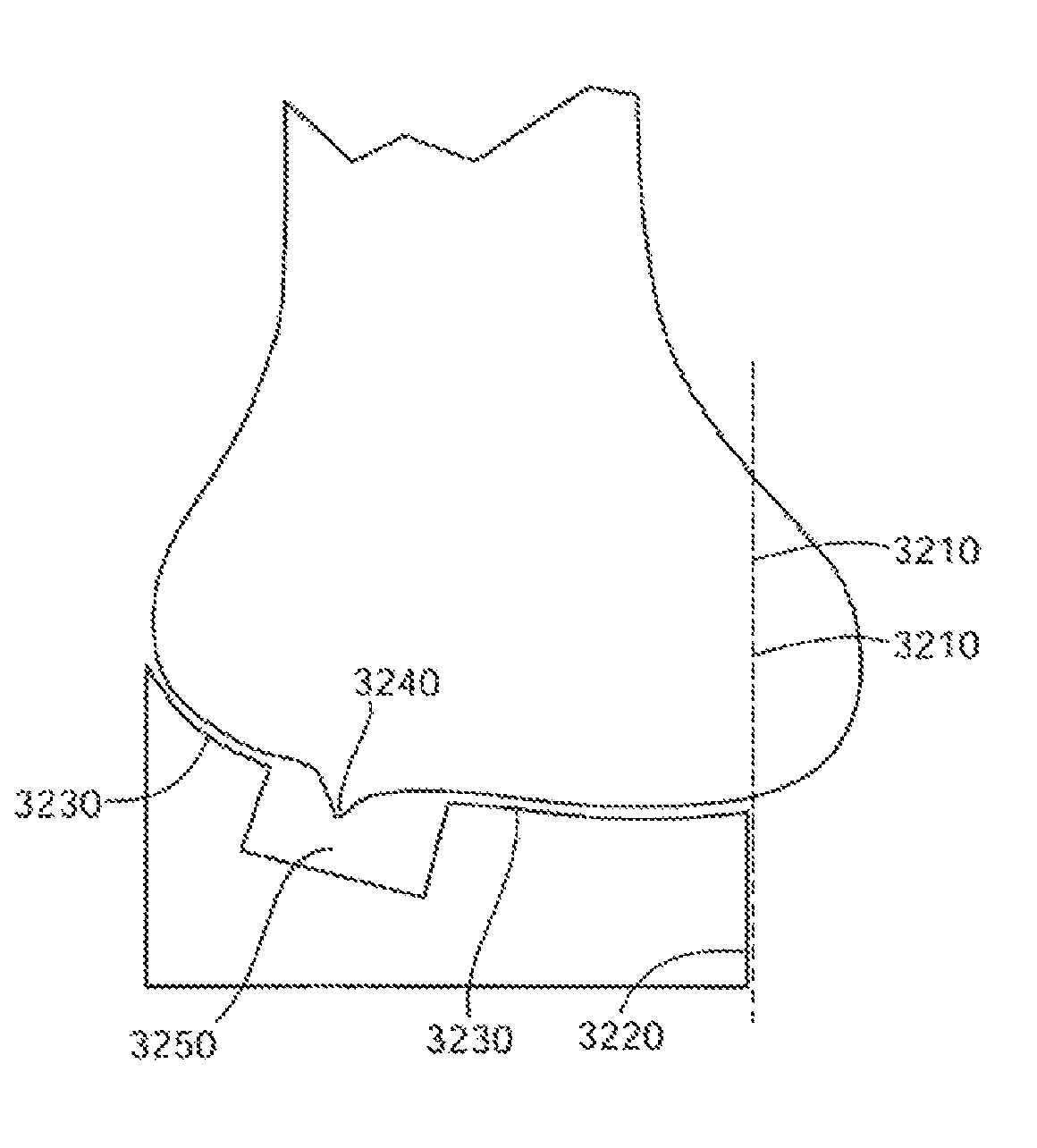
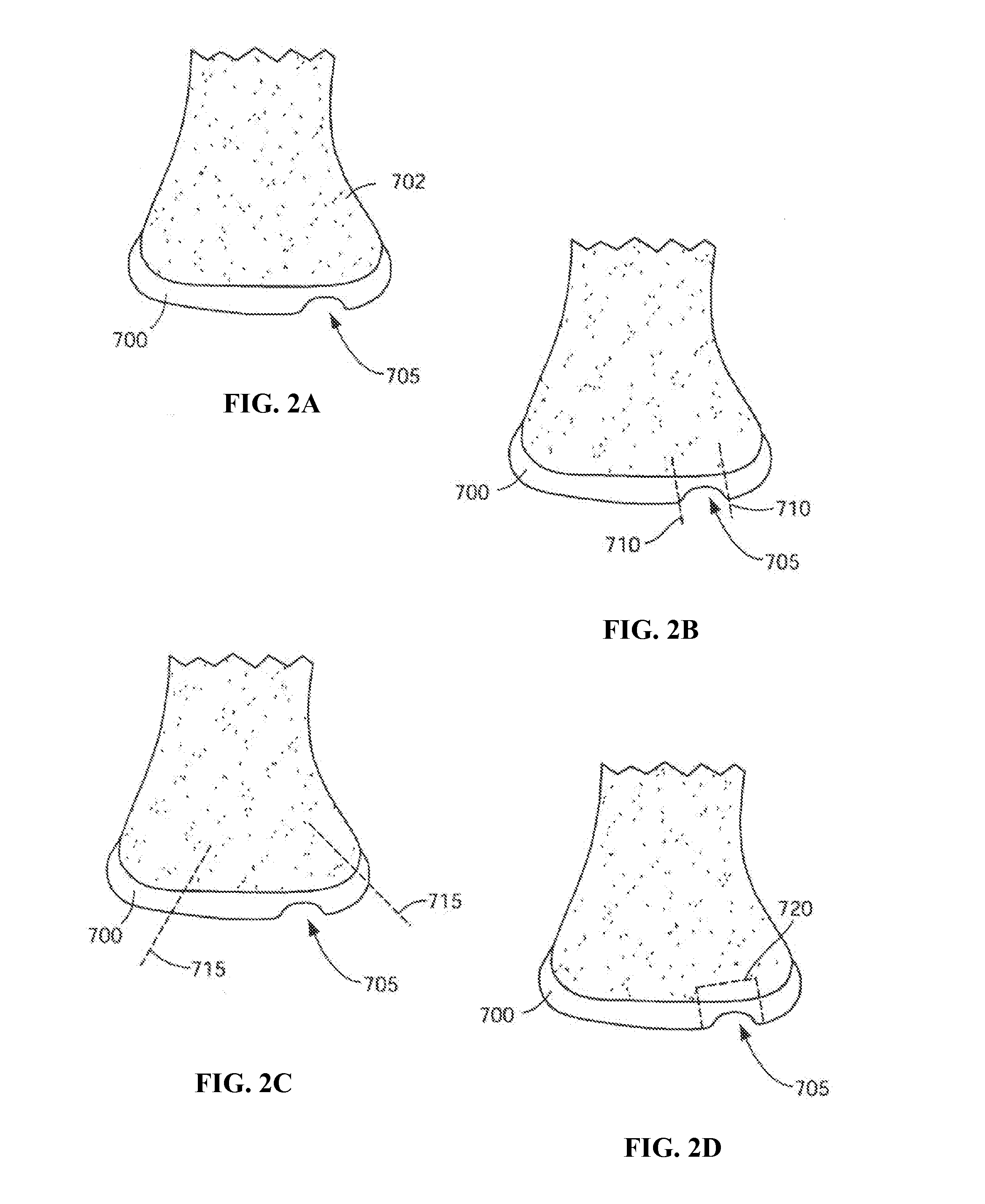
[0629]Anatomical relief features can be used to accommodate or otherwise address osteophytes, subchondral voids, residual normal or diseased cartilage or combinations thereof and other patient-specific defects or abnormalities. In the case of osteophytes, the osteophyte can be integrated into the shape of the bone or joint facing surface of the implant component or guide tool. FIGS. 52A and 52B are exemplary drawings of an end of a femur 1010 having an osteophyte 1020. In the selection and / or design of an implant component for a particular patient, an image or model of the patient's bone that includes the osteophyte or other surface feature can be utilized as a model for creating, designing and / or selecting an implant and / or surgical tool having one or more conforming surfaces. If desired, the portion of the image having the surface feature may be modified, transformed, cross-referenc...


PUM

PropertyMeasurementUnit
thicknessaaaaaaaaaa
timeaaaaaaaaaa
temperaturesaaaaaaaaaa

Abstract

Disclosed herein are methods, compositions and tools for repairing articular surfaces repair materials and for repairing an articular surface. The articular surface repairs are customizable or highly selectable by patient and geared toward providing optimal fit and function. The surgical tools are designed to be customizable or highly selectable by patient to increase the speed, accuracy and simplicity of performing total or partial arthroplasty.

Description

RELATED APPLICATIONS[0001]This application claims the benefit of U.S. Provisional Patent Application Ser. No. 61 / 491,162 to Wong et al, filed May 27, 2011, and entitled “Patient Selectable Joint Arthroplasty Devices and Surgical Tools Incorporating Anatomical Relief.”[0002]This application further claims the benefit of U.S. Provisional Patent Application Ser. No. 61 / 443,155 to Bojarski et al, filed Feb. 15, 2011, and entitled “Patient-Adapted and Improved Articular Implants, Designs and Related Guide Tools.”[0003]This application is also a continuation-in-part of U.S. Ser. No. 11 / 671,745 to Lang et al, entitled “Patient Selectable Joint Arthroplasty Devices and Surgical Tools,” filed Feb. 6, 2007 now U.S. Pat. No. 8,066,708, which claims the benefit of U.S. Ser. No. 60 / 765,592 entitled “Surgical Tools for Performing Joint Arthroplasty” filed Feb. 6, 2006; U.S. Ser. No. 60 / 785,168, entitled “Surgical Tools for Performing Joint Arthroplasty” filed Mar. 23, 2006; and U.S. Ser. No. 60 / 7...

Claims


Application Information

Patent Timeline
Patent Type & Authority Patents(United States)
IPC IPC(8): B23P17/04A61B17/56
CPCA61B19/5244A61B17/1675A61B17/175A61B17/1666A61B2019/508A61B5/4533A61B17/154A61B5/4528A61B17/1746A61B19/50A61B5/4523A61B17/155A61B2019/505A61B2017/1778A61F2/38A61B17/157A61B2017/568A61B5/4514A61B17/158A61F2/30756A61F2/30942A61B17/1703Y10T29/49A61B34/20A61B17/1778A61B34/10A61B2034/105A61B2034/108A61B2034/102A61B2034/104B33Y80/00B33Y70/00A61F2/3859A61F2/389A61F2002/3069A61B2034/2065A61F2/46
Inventor WONG, TERRANCEBOJARSKI, RAYMOND A.STEINES, DANIELLANG, PHILIPP
Owner CONFORMIS
Learn More